

1. How the Plasma Generator Circuit Works
MAXMAC’s bipolar plasma modules accept low-voltage DC power and generate the high voltage needed at the positive and negative emitters. The conversion stage sits inside the module, so the OEM controller supplies power and controls operation through the selected product’s interface.
High-voltage conversion: M1801
The M1801 diagram below shows the path from the power input to the discharge electrodes. The stabilized supply feeds an AC circuit and a boost stage. A separate ON/OFF input lets the host switch ion generation while keeping the main supply connected.
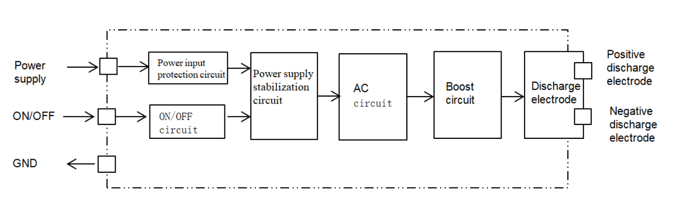
This arrangement gives the host a low-voltage control connection while the module handles high-voltage generation. For the ion-generation mechanism itself, see How Does a Plasma Ion Generator Work?
Input protection and filtering: B02
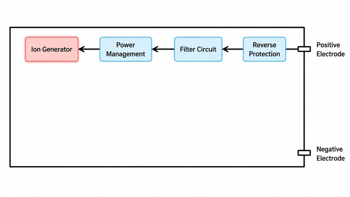
B02’s functional diagram includes reverse protection and a filter circuit ahead of power management. The host turns the module on or off by switching its supply. Its power switch must accommodate the startup current shown in the product table below.
Enable control and status feedback: M96
M96 adds two enable inputs and a DIG diagnostic output. Pins 1 and 2 provide ground and power; pins 3 and 4 accept the control signals, and pin 5 returns the diagnostic signal.
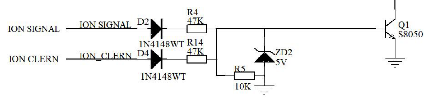
Applying 9–16 V to either enable input starts ion generation. When both inputs are grounded or left floating, ion generation is inactive. The input circuit below shows the two signals entering the control stage. A low-voltage MCU needs a suitable driver to supply the specified enable level.
During normal operation, 3 V < VDIG < 5 V, with approximately 4.8 V described in the specification. Its recommended external load is at least 1 MΩ. The host input must tolerate the DIG voltage and meet that load requirement.
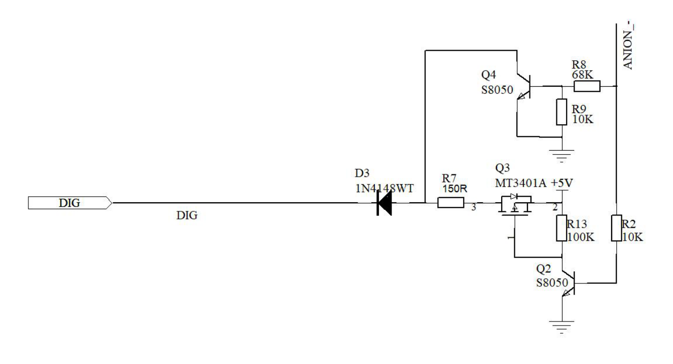
A DIG reading below 3 V can indicate either inactivity or a fault. The controller must therefore interpret it together with the enable command. DIG reports module status; it does not measure the ion concentration delivered into the duct.
2. Which MAXMAC Configuration Fits Your Design?
A complete module provides a defined interface for the host controller. Choose the control method that fits your board using the comparison below. The M96 circuit example explains how a module with status feedback differs from a simple switched-power design.
The independent JDOPI120255AA high-voltage supply is an option for an OEM-developed board. Its lead-connected emitters can sit separately from the pack body, allowing the release points to be positioned in the air path. The OEM develops the surrounding control and mounting arrangement.
| Product | DC Input | Current | Control / Feedback | Product Details |
|---|---|---|---|---|
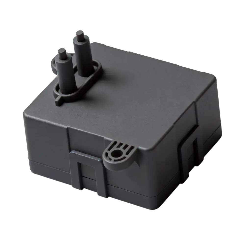 M96 M96 |
9–16 VDC | ≤40 mA operating ≤0.1 mA standby | Two enable inputs Either input activates ion output DIG status feedback |
Check More |
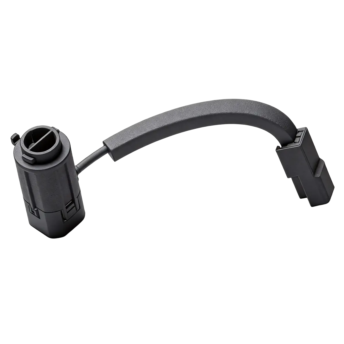 B02 B02 |
9–16 VDC | ≤50 mA operating ≤100 mA startup | Two-pin power switching Supply ON / OFF; no dedicated feedback pin |
Check More |
 M1801 M1801 |
10–16 VDC | 10 mA rated 12 V, 25°C ± 5°C 50 mA maximum 12 V, −30 to 80°C | Independent ION terminal Separate power and ON / OFF control; no dedicated feedback pin |
Check More |
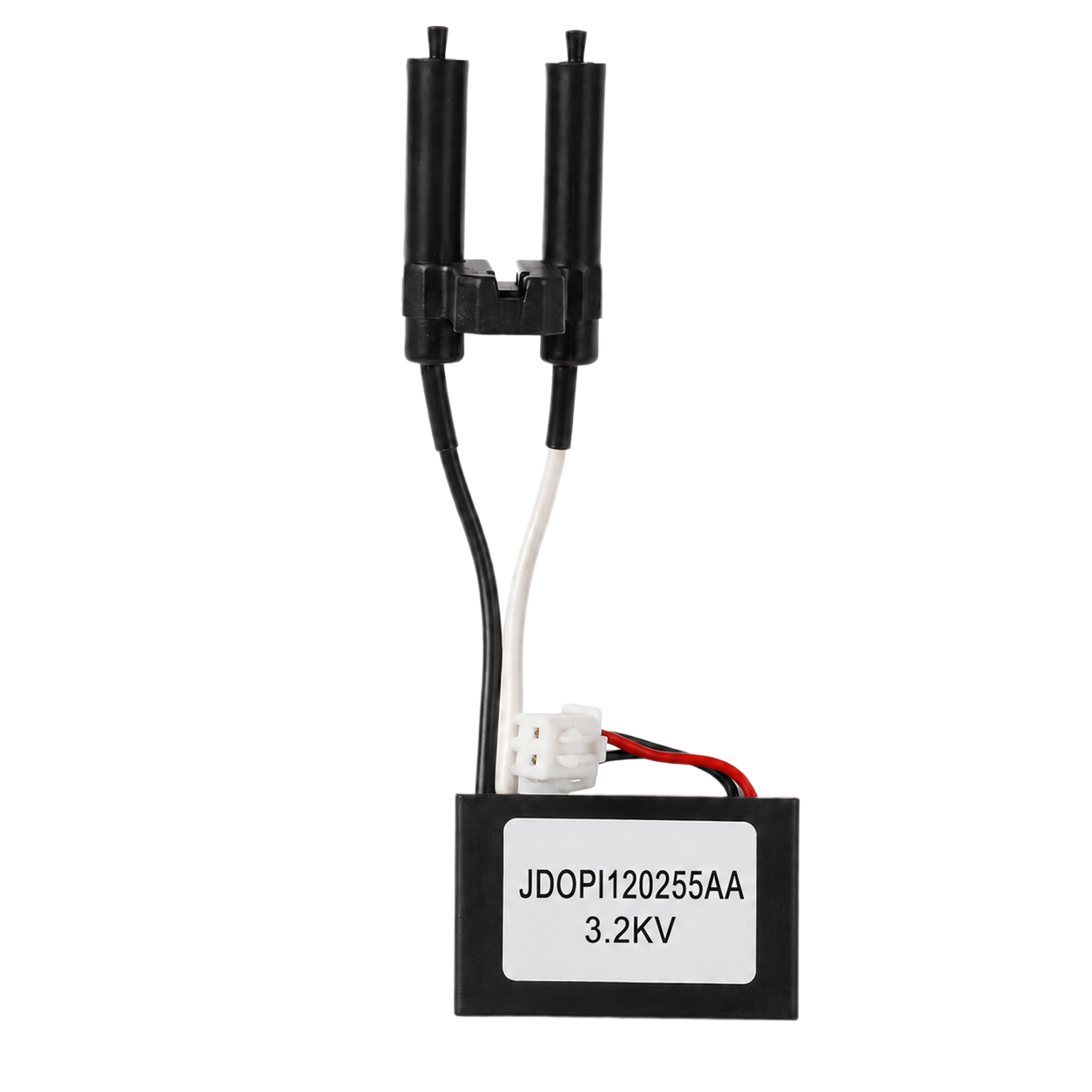 JDOPI1202 JDOPI1202 |
11.4–12.6 VDC | 60 mA maximum | Host-controlled power supply Bipolar high-voltage output leads; no dedicated feedback pin |
Check More |
Check the available supply against the full input range in the table. The independent pack has a narrower range than the complete modules, so a nominal 12 V source may need regulation. Its positive and negative outputs are specified as +2.0 to +3.2 kVo-p and −2.0 to −3.2 kVo-p.
Use the product links to review the selected module’s connector drawing before laying out the host interface. The table describes the listed hardwired configurations; it does not imply a standard LIN connection.
3. Selection Notes for Automotive, HVAC and Appliance OEMs
Automotive OEM: does the controller need feedback?
If the cabin controller needs to monitor module operation, M96 provides a DIG output. Read this signal together with the enable command, as described above. A system that only needs to switch ion generation can use a simpler control arrangement from the comparison table.
Temperature limits also affect this choice. M96 and B02 specify −40 to 85°C operation, while M1801’s installation parameter table specifies −30 to 80°C. Match the limit to the actual mounting location.
HVAC OEM: where will ion output be measured?
For a duct installation, define the measurement position before comparing output figures. A reading close to the emitter does not establish the concentration at a downstream outlet. Evaluate the selected module in the intended air path, using a measurement point relevant to the equipment’s treatment area.
If the fan operates at several speeds, include those conditions in the evaluation. This provides more useful selection evidence than choosing a module from its highest published concentration alone.
Appliance OEM: can the emitters fit the enclosure?
In a compact appliance, the preferred emitter position may be some distance from the mainboard. The independent pack’s lead-connected emitters allow the pack body to sit elsewhere in the housing. This can help an air-purifier design place its emitters near the outlet without moving the control board.
Check the environmental rating at that position. JDOPI120255AA specifies non-condensing operation, so an installation exposed to condensation needs a different arrangement or a separately evaluated configuration.
4. How to Compare Ion Output
Ion concentration depends on measurement distance and airflow. Compare products under matching test conditions before using their output figures to select a module.
| Product / Data | Measurement Distance | Airflow Speed |
|---|---|---|
| M96 specification | 20 cm from emitter | 3 m/s |
| B02 electrode rating | At the electrode | Not stated for this rating |
| B02 measured results | 15 cm | 35 m/s |
| JDOPI120255AA | 100 cm from electrode to counter | 5 m/s at the counter |
B02’s electrode rating and its measured results are separate datasets. Keep each concentration figure with its own test conditions rather than combining the rating with the distance from another test.
Validate ion output in your actual equipment using an agreed measurement position and airflow condition. Ion concentration data does not replace ozone testing; obtain the ozone results for the selected configuration.
Discuss Your OEM Integration
Send us your available supply voltage and control requirements. A drawing of the installation space will help us assess the module fit.
Contact MAXMAC EngineeringProduct specifications used in this guide
- M96 Plasma Module Specification (PDF)
- B02 Plasma Module Specifications (PDF)
- M1801 Plasma Module Specification (PDF) — electrical and installation parameter tables.
- JDOPI120255AA High-Voltage Pack Specification (PDF)