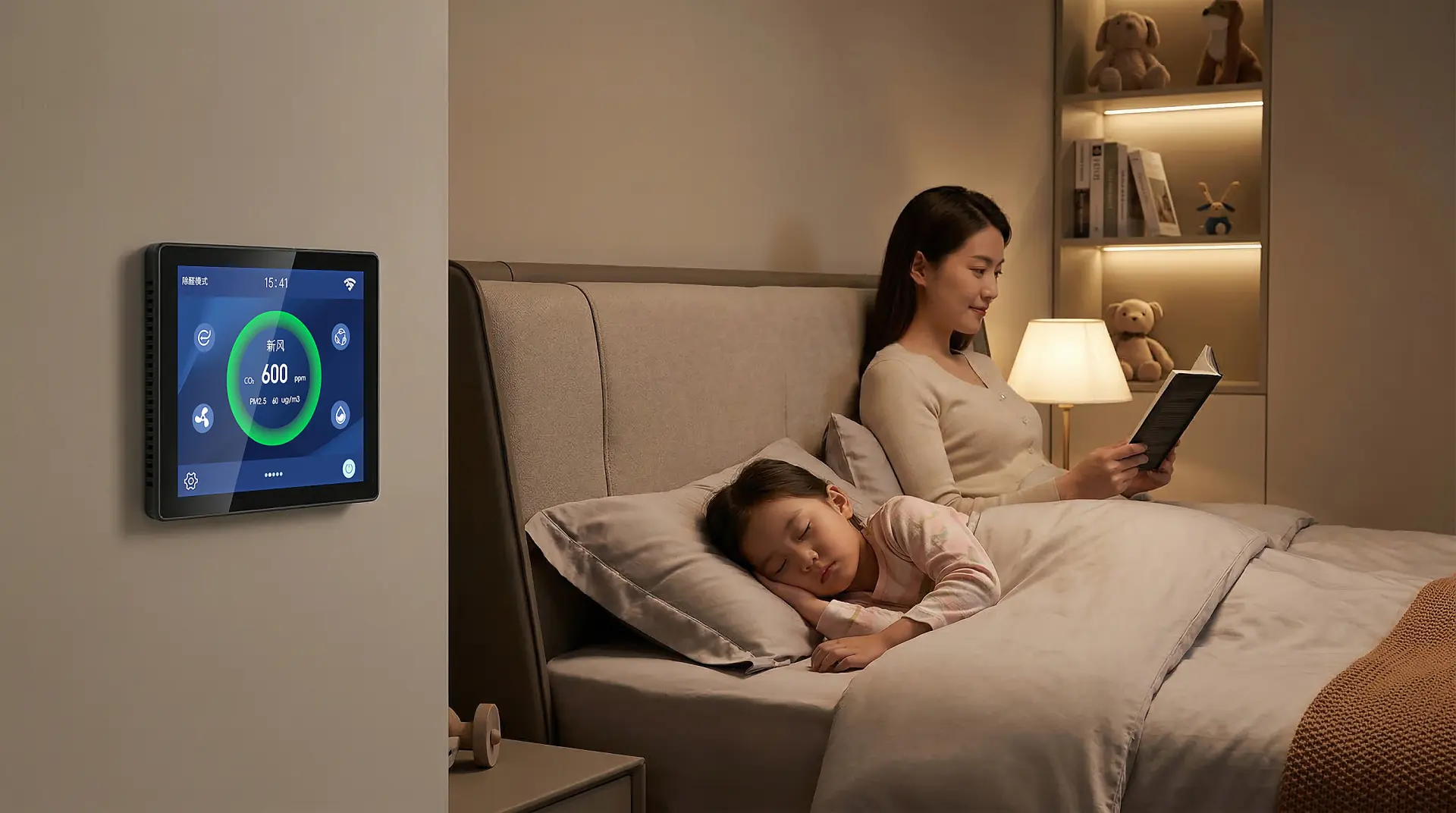
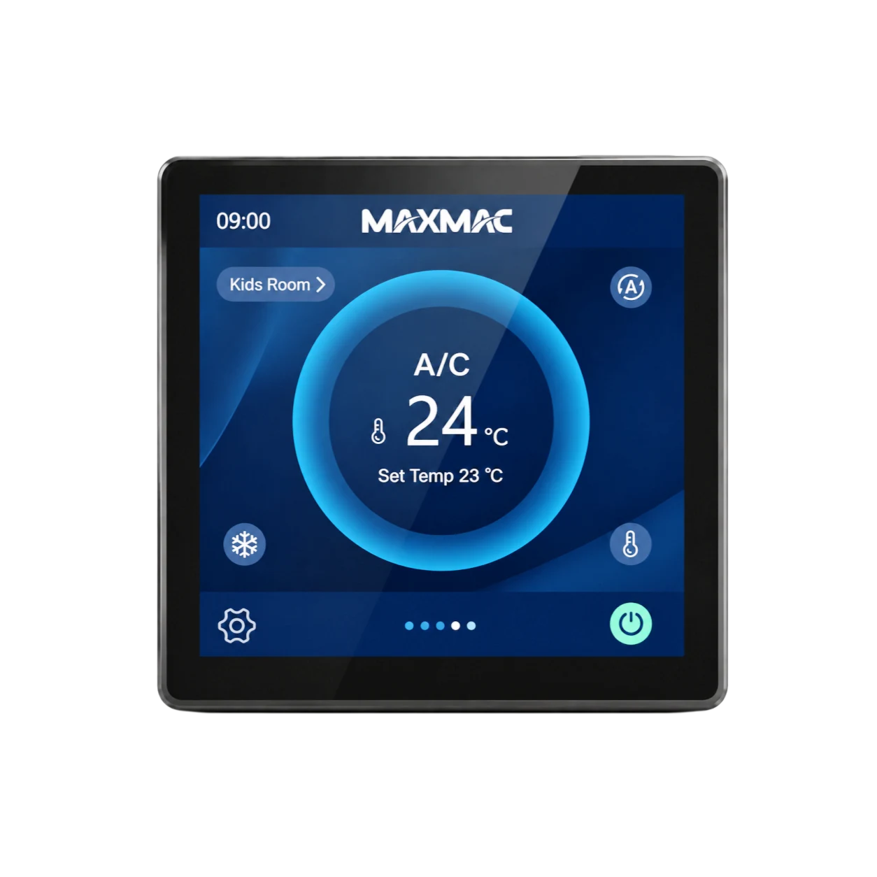
MAXMAC programmable thermostat with integrated multi-sensor indoor air quality monitoring

PROGRAMMABLE THERMOSTAT

Programmable Thermostats Manufacturer & OEM Supplier with Integrated Multi-Sensor IAQ Platform

As a professional HVAC control and sensing solutions provider, MAXMAC supplies next-generation programmable thermostats and smart environmental control solutions to customers worldwide. Going beyond conventional digital thermostats, our programmable thermostat platform can integrate MAXMAC multi-in-one air quality sensing for real-time monitoring of PM2.5, CO₂, TVOC, temperature and humidity. A single device can provide intelligent scheduled control of air conditioning, fresh-air ventilation, underfloor heating and fragrance systems throughout the home.

Designed for residential, apartment and integrated HVAC projects, MAXMAC programmable smart thermostats can be configured with schedule control, target-temperature settings, fan-speed linkage, WiFi or RS485 communication, and multi-sensor indoor air quality monitoring according to project requirements. Production follows strict ISO 9001 and IATF 16949 quality management systems, supported by a national CNAS-accredited laboratory for environmental simulation, aging and consistency testing from the earliest stages of product development. All MAXMAC thermostat products are designed to meet CE and RoHS requirements, helping OEM customers develop reliable, high-performance smart thermostat product lines.

PROGRAMMABLE THERMOSTAT SERIES

Explore Our Next-Generation Programmable Smart Thermostats

MAXMAC programmable thermostats for home, apartment and integrated HVAC projects can be customized with WiFi, RS485, Modbus, Zigbee, RF and Ethernet connectivity according to project requirements. Programmable WiFi thermostats are well suited to remote app control and connected-home applications. For B2B model selection, MAXMAC can provide a smart thermostat comparison chart based on screen size, communication, sensing and control requirements.

6-A6312-K Wired Digital Programmable Thermostat
6-A6312-K

6-A6312-K Wired Digital Programmable Thermostat

Hardware
4-inch full-color touchscreen
Connectivity
Wired · RS485 · Modbus / Ethernet expandable · No WiFi
Built-in Sensors
Temperature + Humidity

The 6-A6312-K is one of MAXMAC’s wired programmable digital thermostats, built around stable RS485 bus communication. It features a 4-inch full-color touchscreen and integrated temperature and humidity sensing for accurate room-level comfort control. Designed as a wired HVAC control hub, it supports programmable heating and cooling logic while coordinating air conditioning, fresh-air ventilation, underfloor heating and fragrance systems from one interface.

Read more
6-A6314-K Programmable WiFi Thermostat
6-A6314-K

6-A6314-K Programmable WiFi Thermostat

Hardware
4-inch full-color touchscreen
Connectivity
Wireless + Wired · WiFi + RS485 · Modbus / Ethernet expandable
Built-in Sensors
Temperature + Humidity

The 6-A6314-K combines WiFi cloud connectivity with wired RS485 communication to create a flexible programmable WiFi thermostat solution. Its 4-inch touchscreen and built-in temperature and humidity sensing support scheduled comfort control, remote app-based adjustment and room-level HVAC operation. It is well suited to smart apartments, villas and residential projects that require both wireless convenience and wired system reliability.

Read more
6-A6313-K IAQ Programmable Heating Thermostat
6-A6313-K

6-A6313-K IAQ Programmable Heating Thermostat

Hardware
4-inch full-color touchscreen
Connectivity
Wired · RS485 · Modbus / Ethernet expandable · No WiFi
Built-in Sensors
Temperature + Humidity + CO₂ + PM2.5

The 6-A6313-K is a wired programmable heating thermostat with integrated CO₂, PM2.5, temperature and humidity sensing. Its RS485 connection enables stable scheduled temperature control, while real-time IAQ data supports coordinated operation of air conditioning, fresh-air ventilation, underfloor heating and fragrance systems. It is designed for projects where programmable heating control and indoor air quality monitoring need to work together.

Read more
6-A6315-K Wireless Programmable Smart Thermostat
6-A6315-K

6-A6315-K Wireless Programmable Smart Thermostat

Hardware
4-inch full-color touchscreen
Connectivity
Wireless + Wired · WiFi + RS485 · Modbus / RF / Zigbee / Ethernet expandable
Built-in Sensors
Temperature + Humidity + CO₂ + PM2.5

The 6-A6315-K is a fully equipped programmable smart thermostat platform for connected HVAC and smart-home projects. It combines WiFi networking, wired RS485 communication and expandable protocol options with integrated CO₂, PM2.5, temperature and humidity sensing. This model supports remote scheduled control, IAQ monitoring and unified operation of air conditioning, fresh-air ventilation, underfloor heating and fragrance systems from one device.

Read more
6-A2302-H Large-Screen Programmable Room Thermostat
6-A2302-H

6-A2302-H Large-Screen Programmable Room Thermostat

Hardware
6-inch full-color touchscreen
Connectivity
Wireless + Wired · WiFi + RS485 · Modbus / RF / Zigbee / Ethernet expandable
Built-in Sensors
Temperature + Humidity + CO₂ + PM2.5

Among MAXMAC’s large-screen programmable room thermostats, the 6-A2302-H is a premium solution for high-end residential, hotel and apartment projects. Its expansive 6-inch touchscreen provides a clear interface for temperature schedules, IAQ display and multi-system control. With dual WiFi and RS485 communication, it supports remote app control, wired integration and centralized management of air conditioning, fresh-air ventilation, underfloor heating and fragrance systems.

Read more
6-A5601-K Desktop Automatic Thermostat
6-A5601-K

6-A5601-K Desktop Automatic Thermostat

Hardware
4-inch full-color touchscreen · 3000 mAh lithium battery
Connectivity
Wireless · WiFi · RS485 / Modbus expandable
Built-in Sensors
Temperature + Humidity + CO₂ + PM2.5

The 6-A5601-K is a portable desktop automatic thermostat designed for flexible indoor environmental monitoring and remote comfort control. Powered by a 3000 mAh lithium battery, it can be placed where representative room conditions need to be measured instead of being fixed to one wall location. Through WiFi and expandable communication, it can support programmable control of air conditioning, fresh-air ventilation, underfloor heating and fragrance systems while displaying temperature, humidity, CO₂ and PM2.5 data in real time.

Read more

SMART PROGRAMMING & MULTI-SYSTEM CONTROL

One Programmable Thermostat for Air Conditioning, Fresh Air, Underfloor Heating, Fragrance & Engineering Control

MAXMAC programmable thermostats bring scheduled temperature control and multi-system indoor management together in one interface. Users can configure a 7-day programmable thermostat schedule around daily occupancy and comfort requirements while managing connected air-conditioning, fresh-air ventilation, underfloor-heating and fragrance equipment from one central control panel.

Each control branch presents the settings relevant to its connected equipment. For projects requiring programmable thermostats for heat pumps, MAXMAC can map supported operating modes, temperature targets and control commands to the approved equipment interface. Available systems, zones, communication functions and programmable options are defined according to the approved project configuration.

MAXMAC programmable thermostat coordinating five indoor control branches

Air Conditioning

Mode, temperature, fan speed and zone control

Select the active air-conditioning zone and configure its operating mode, target temperature and fan speed. The selected operating mode applies across the connected air-conditioning system, while temperature and fan-speed settings can be adjusted for the active zone.

  1. Active air-supply zone
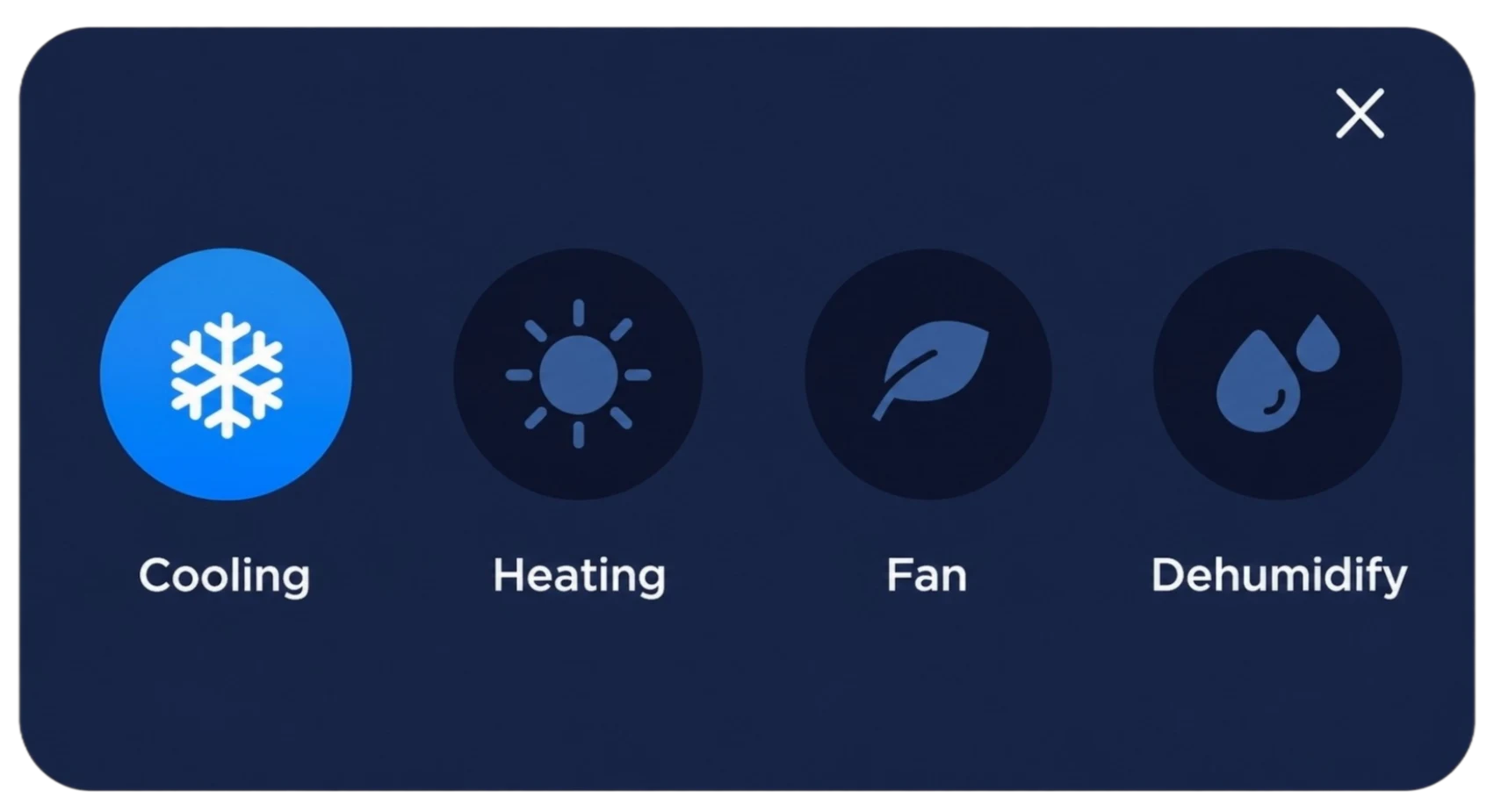
  2. Cooling mode
  3. Heating mode
  4. Fan mode
  5. Dehumidification mode
  6. Target temperature
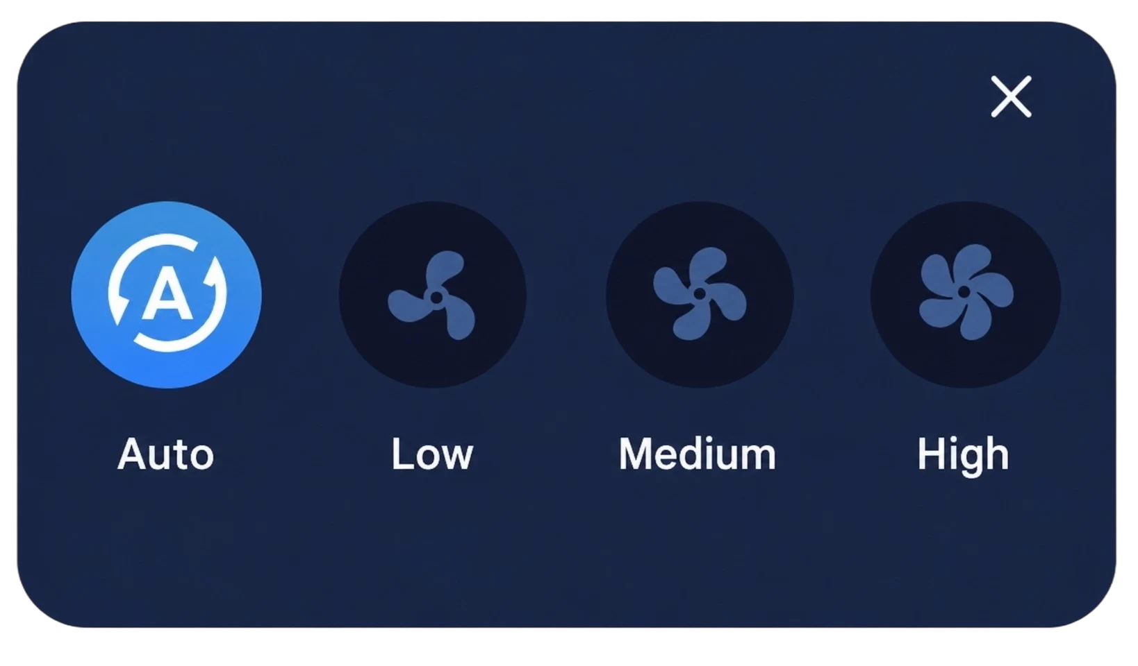
  7. Automatic, low, medium or high fan speed
  8. Equipment on/off status

PRODUCT ARCHITECTURE & MULTI-SENSOR INTEGRATION

Accurate Room Thermostat with Integrated Sensor Architecture & Onboard Multi-Sensor Platform

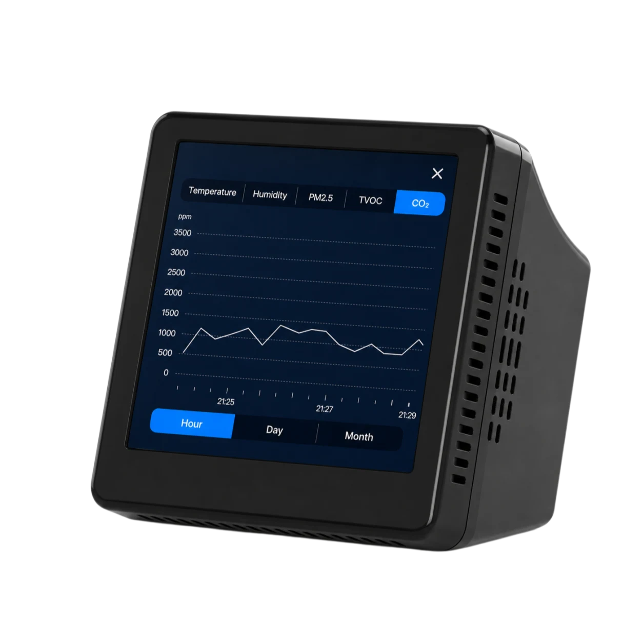
Precise HVAC control begins with stable and reliable environmental data. MAXMAC thermostats integrate a multi-sensor IAQ platform that accurately monitors temperature, humidity, CO₂, PM2.5 and TVOC conditions in individual rooms in real time.

Optimized airflow paths, thermal isolation and proprietary calibration algorithms help minimize interference from internal heat generation and surrounding airflow. By supplying HVAC systems with representative, high-accuracy environmental data, the platform enables connected HVAC equipment to respond more intelligently and operate more efficiently.
Exploded programmable thermostat showing touchscreen, enclosure, PCB and onboard sensors
1

4-Inch 480 × 480 dpi Full-Color Capacitive Touchscreen

2

PC+ABS, UL 94 HB Flame-Retardant Housing

3

Onboard Temperature, Humidity and Optional IAQ Sensors

4

Dual RS485, Modbus-Compatible, Optional WiFi

5

M4 Screw Fastening

Customize Your Programmable Thermostat

KEY SENSOR ENGINEERING

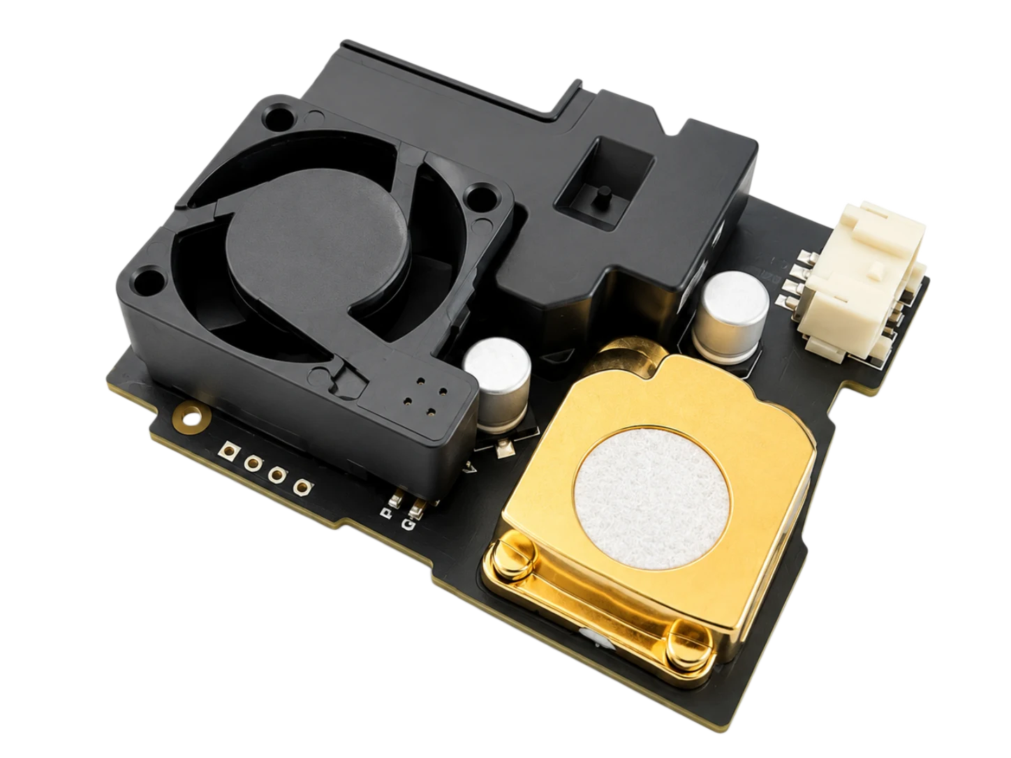
MAXMAC IAQ multi-sensor development board for onboard programmable thermostat integration

Direct PCB Onboard Integration

1

High-Precision Sensor Array

Digital temperature, humidity, CO₂, PM2.5 and TVOC sensing elements and compact modules are integrated directly with the main control PCB to form a space-efficient, multi-in-one programmable thermostat sensor platform. Eliminating complex external probe wiring simplifies installation and helps keep the wall finish clean and uncluttered.

Explore Multi-Sensor Modules
Wireless thermostat enclosure airflow and sensor sampling cavity design

Thermal Isolation & Structural Ventilation

2

Precision Airflow Cavity

Purpose-designed convection openings along the side and bottom of the enclosure allow room air to flow naturally through the internal programmable thermostat sensor sampling zone. The structured airflow cavity helps isolate sensing from heat generated by internal electronics, supporting a faster response and more representative room measurements.

Multi-point programmable thermostat sensor factory calibration curve

Factory Calibration & Real-Time Data Calibration

3

Multi-Point Factory Calibration

Every integrated programmable thermostat sensor module is calibrated in high-precision temperature, humidity and gas calibration chambers before shipment to ensure consistent environmental data acquisition. Built-in anti-drift algorithms and ABC (Automatic Baseline Calibration) maintain stable, high-accuracy output during long-term indoor operation, supporting a design target of up to 15 years of maintenance-free operation.

THERMOSTAT PRODUCT INFORMATION

Integrated Sensor Specifications and Package Contents for Programmable Thermostats

Built-in Sensor Specifications

MeasurementOperating PrincipleRangeResolutionAccuracy
PM2.5Laser scattering0–999 μg/m³1 μg/m³±15 μg/m³ at ≤100; ±15% above 100
CO₂NDIR infrared400–9999 ppm1 ppm±(50 ppm + 5% of reading)
TemperatureCMOSens®−20°C to 85°C1°C±2°C
HumidityCMOSens®1–99% RH1% RH±5% RH
TVOCSemiconductor conductivity1–30,000 ppb1 ppb—

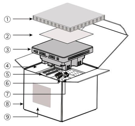
Package Contents

ItemDescriptionQuantity
1Pearl-cotton protective separator1
2Installation manual, certificate and warranty card1
3Integrated IAQ thermostat controller1
4Pearl-cotton inner tray1
5M4 × 30 mm mounting screws2
64-pin wiring terminal1
72-pin wiring terminal1
8Outer carton1
9Outer-carton label1
Exploded view of MAXMAC programmable thermostat package contents

THERMOSTAT INSTALLATION GUIDE

Programmable Thermostat Installation Guide

Before installation, confirm the power supply, controlled equipment, communication wiring sequence, wall-box dimensions and sensor sampling position. Disconnect the power supply, separate the front and rear assemblies, and complete the power and communication wiring according to the terminal definitions. Secure the rear assembly to an 86-type wall box or the specified mounting position, reinstall the front assembly, restore power and complete system commissioning.

1Separating the programmable thermostat front frame from the rear assembly
STEP A

Separate the Front and Rear Assemblies

Insert a flat-head screwdriver into the lower separation slot. Support the front frame to protect the LCD and prevent it from falling, then gently pry and slowly lift the front frame away from the rear assembly.

2Programmable thermostat power and communication terminal wiring definitions
STEP B

Complete Power and Communication Wiring

Connect power, RS485 and required control cables to the specified terminals. Follow the project-specific programmable thermostat instructions because valves, actuators, manifold controllers and HVAC integrations may use different wiring.

3Mounting the programmable thermostat rear assembly with the sensor port facing down
STEP C

Mount the Rear Assembly in the Wall Box

Fit the rear assembly into an 86-type wall box with the sensor sampling port facing downward. Secure it to a flat wall so the sensor can measure representative room conditions.

4Snapping the programmable thermostat front frame onto the rear assembly
STEP D

Snap the Front Assembly into Place and Commission

Secure the front frame and restore power. Commission the heating and connected systems. Any programmable thermostat manual or manual PDF must match the model, terminals and final system configuration.

Installation Requirements

  1. This product must be installed by a qualified professional. Improper installation may damage the equipment.
  2. Verify that the control panel supply voltage and power rating meet the operating requirements.
  3. Install the control panel approximately 1.5 meters above the floor in a well-ventilated location.

Do Not Install in the Following Locations

  • Poorly ventilated locations, including corners and behind doors.
  • Near heating or cooling pipes, direct sunlight or other heat sources.
  • Locations with unusually low or high indoor temperatures, including walls in direct contact with the outdoors.
Diagram showing unsuitable programmable thermostat locations behind a door and in an unventilated corner

INTUITIVE MULTI-SYSTEM CONTROL

Programmable Thermostat Control: Precision HVAC Multi-System Integration

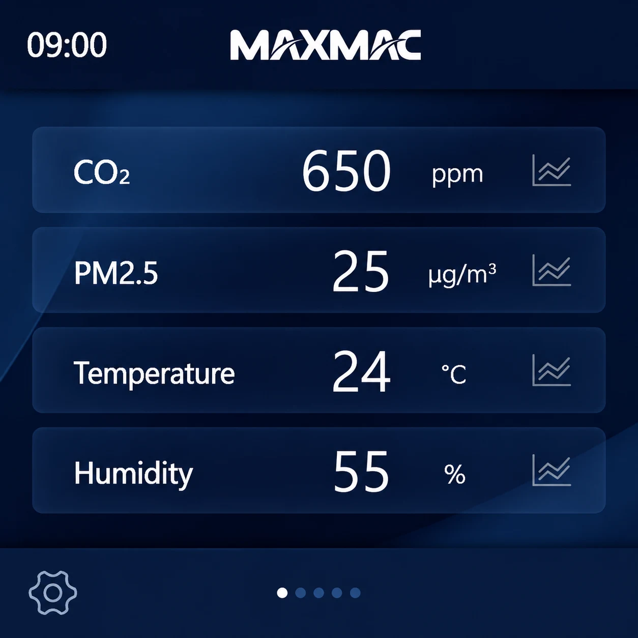
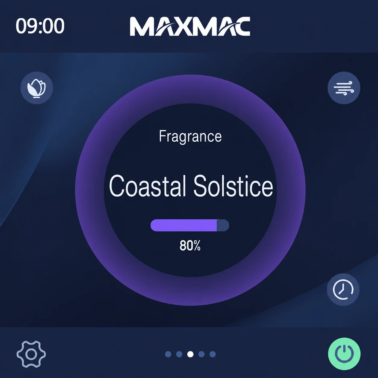
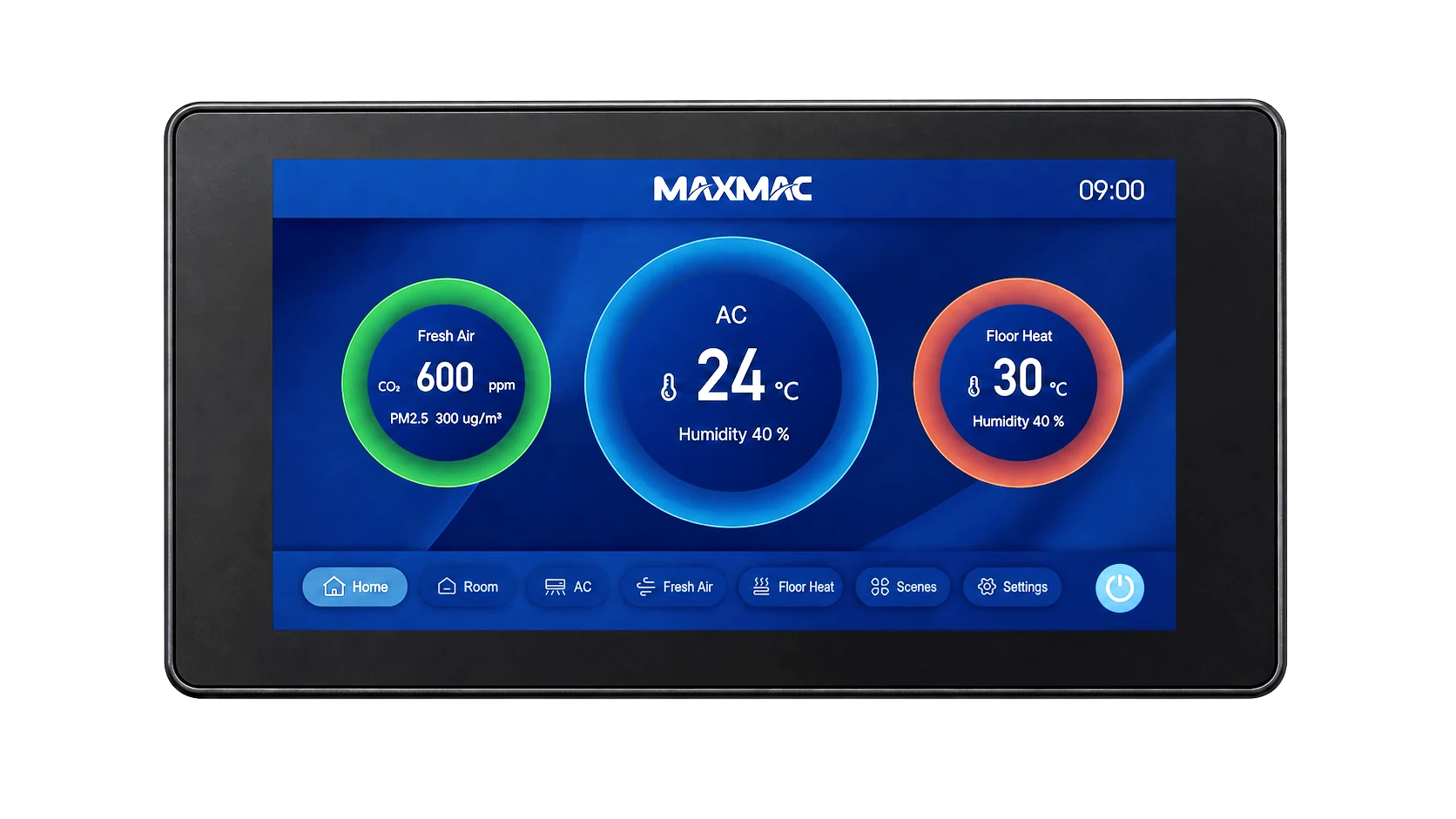
The main interface brings together air quality monitoring, fresh-air ventilation, fragrance, air conditioning and underfloor heating. Swipe left or right to move between function pages and operate the connected equipment. Available screens may vary according to the devices connected and the requirements of each project.

Wireless thermostat air quality monitoring interface showing carbon dioxide, PM2.5, temperature and humidity
Air Quality
Wireless thermostat fresh-air ventilation control interface
Fresh Air Ventilation
Wireless thermostat fragrance system control interface
Fragrance System
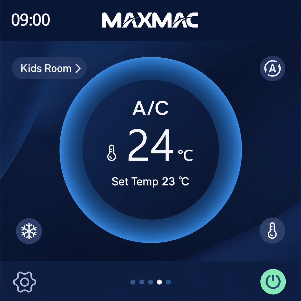
Wireless thermostat air-conditioning control interface
Air Conditioning
Wireless thermostat underfloor heating control interface
Underfloor Heating

Select the settings icon in the lower-left corner of the home screen to open the settings page.

Select the power icon in the lower-right corner to switch the corresponding equipment on or off. A highlighted icon indicates that the equipment is on; a dimmed icon indicates that it is off.

Open the main settings screen and select the corresponding icon to access each settings page. Use Time Settings to set the system clock, Backlight Settings to adjust LCD brightness and screen-on duration, and About to view the software version. Select More to open Engineering Configuration. This function is intended exclusively for commissioning by qualified professionals.

Wireless thermostat main settings interface with time, backlight, more and about options
Wireless thermostat system time settings interface
Wireless thermostat LCD brightness and screen-on duration settings interface

Underfloor Heating Control

The underfloor heating home screen displays the current room temperature and target temperature. Select the icon outside the temperature ring to adjust the operating settings. If the i fault icon appears, communication with the underfloor heating equipment is abnormal.

Underfloor heating home screen showing room temperature and target temperature
Underfloor heating target temperature adjustment interface

Set the Underfloor Heating Target Temperature

Fresh Air Ventilation Control

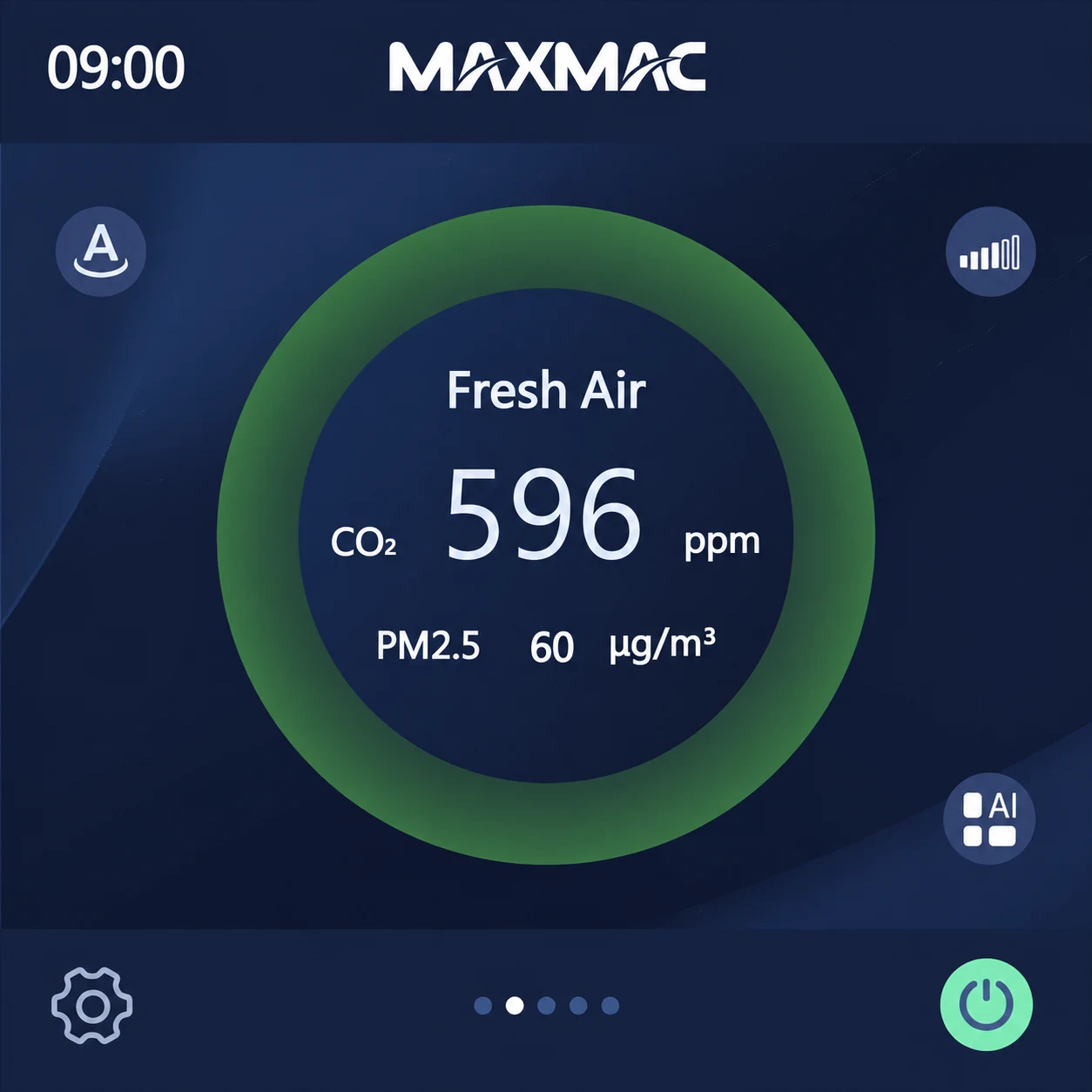
The fresh-air home screen displays the current indoor CO₂ and PM2.5 readings. Select the icons outside the ring to adjust the operating settings. If the i fault icon appears, communication with the connected fresh-air equipment is abnormal.

Fresh-air ventilation home screen showing carbon dioxide and PM2.5 readings
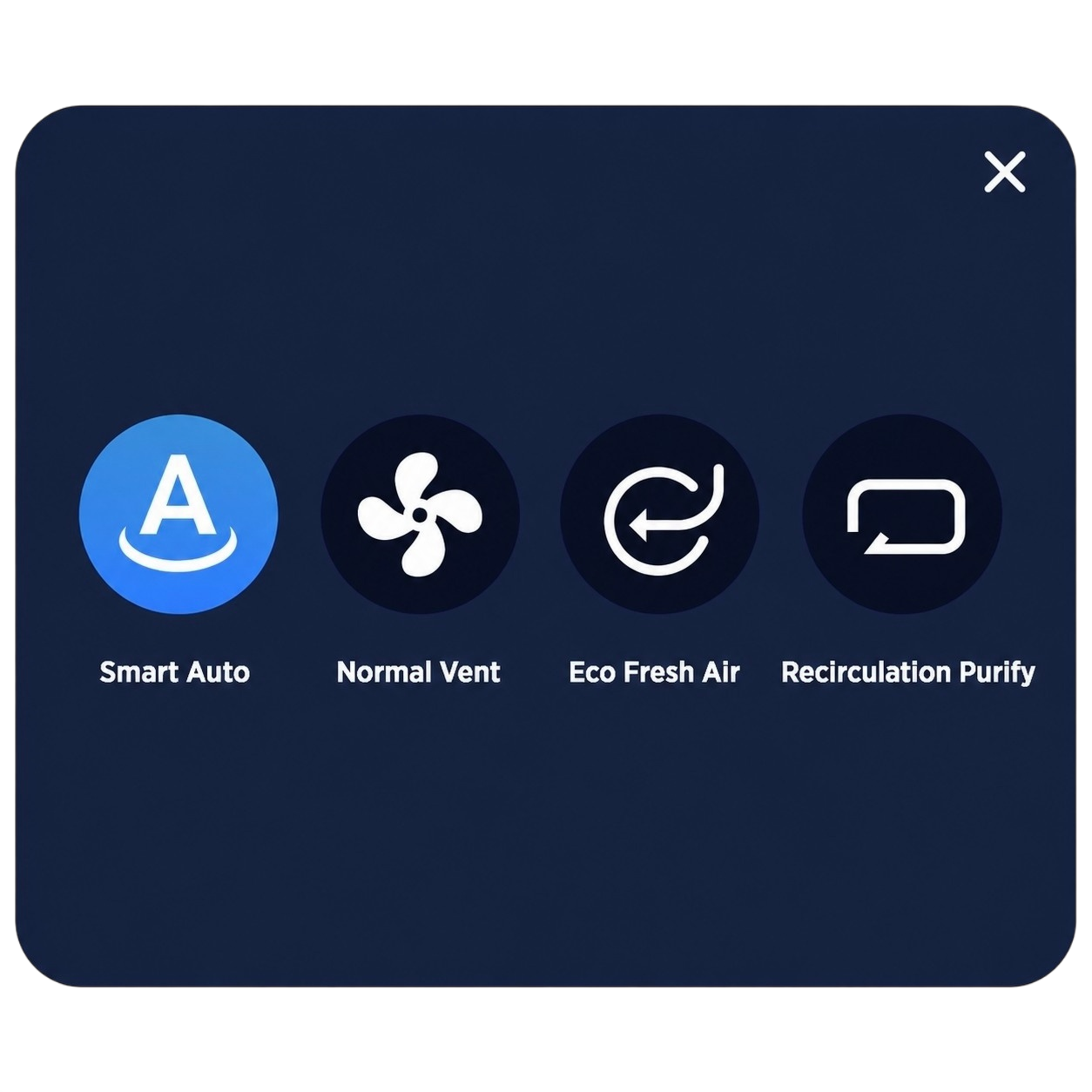
Ventilation operating mode icon Fresh-air ventilation operating mode selection interface
  • Smart Auto: Automatically adjusts airflow according to indoor air quality.
  • Standard Ventilation: Exchanges indoor and outdoor air directly without heat recovery.
  • Energy-Saving Fresh Air: Uses heat recovery to balance ventilation and energy efficiency.
  • Recirculation Purification: Filters recirculated indoor air without introducing outdoor air.
Fresh-air fan speed icon Fresh-air ventilation fan speed adjustment interface
  • Drag the slider to set the fan speed. In Smart Auto mode, the fan speed changes automatically.
Fresh-air zone control icon Fresh-air ventilation zone control interface
  • Zone control becomes available after the motorized air valves for each supply-air zone have been configured.
  • During installation, each air valve must use a unique RS485 address.

Fresh Air Ventilation Control — Zone Control

Zone control distributes airflow by adjusting the opening of the motorized air valve in each zone together with the total airflow supplied by the fresh-air unit. The system provides three operating modes. Both Smart and Manual modes allow unused zone valves to be switched off.

Smart Mode: Uses air-quality data and an intelligent algorithm to adjust the opening of each connected zone valve automatically.

Standard Mode: Opens each valve to the position defined during project commissioning; valve opening cannot be adjusted from this screen.

Manual Mode: Allows the user to adjust the opening of each zone valve independently.

Valve opening is adjustable from 0% to 100% (0% fully closed and 100% fully open) in 5% increments.

Smart mode fresh-air zone control interface
Standard mode fresh-air zone control interface
Manual mode fresh-air zone control interface

Air Conditioning Control

The air-conditioning home screen displays the current temperature and target temperature for the selected zone. Select the icons outside the temperature ring to adjust the operating settings. If the i fault icon appears, communication with the connected air-conditioning equipment is abnormal.

Air-conditioning home screen showing current and target zone temperature
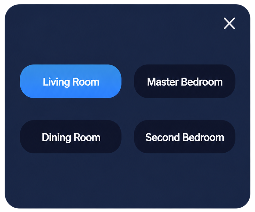
Air-conditioning zone selection icon Air-conditioning zone selection interface

Switch the active air-supply zone to adjust the temperature and fan speed for that zone.

Air-conditioning operating mode icon Air-conditioning operating mode selection interface

Set the air-conditioning operating mode. This is a system-wide setting and applies to every zone.

Air-conditioning fan speed icon Air-conditioning fan speed selection interface

Set the air-conditioning fan speed for the selected zone.

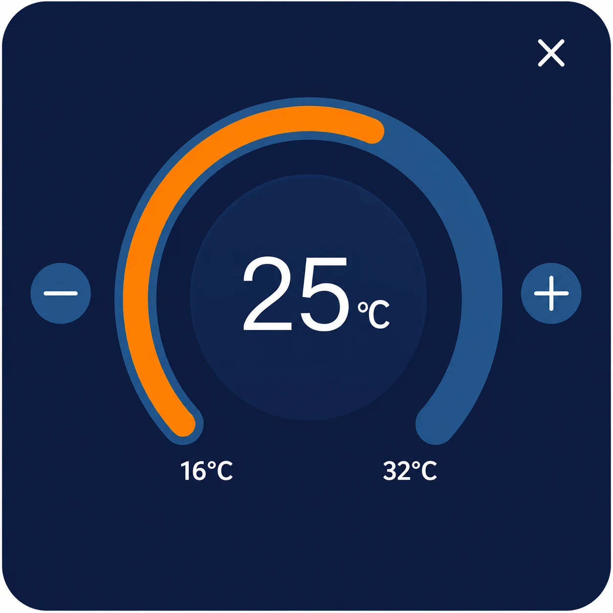
Air-conditioning target temperature icon Air-conditioning target temperature adjustment interface

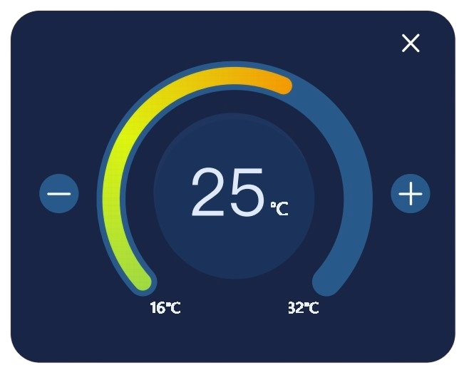
Set the target operating temperature for the selected zone.

Fragrance Control

The fragrance home screen displays the active fragrance and remaining cartridge level. Select the icons outside the fragrance ring to configure fragrance type, intensity and operating schedule. If the i fault icon appears, communication is abnormal or the fragrance cartridge has not been recognized. Replace the cartridge when the remaining level reaches 0%.

Fragrance control home screen showing active fragrance and remaining cartridge level
Fragrance type selection icon Fragrance type selection interface

Switch the active fragrance. The highlighted fragrance is active; this option applies to connected dual-channel fragrance generators.

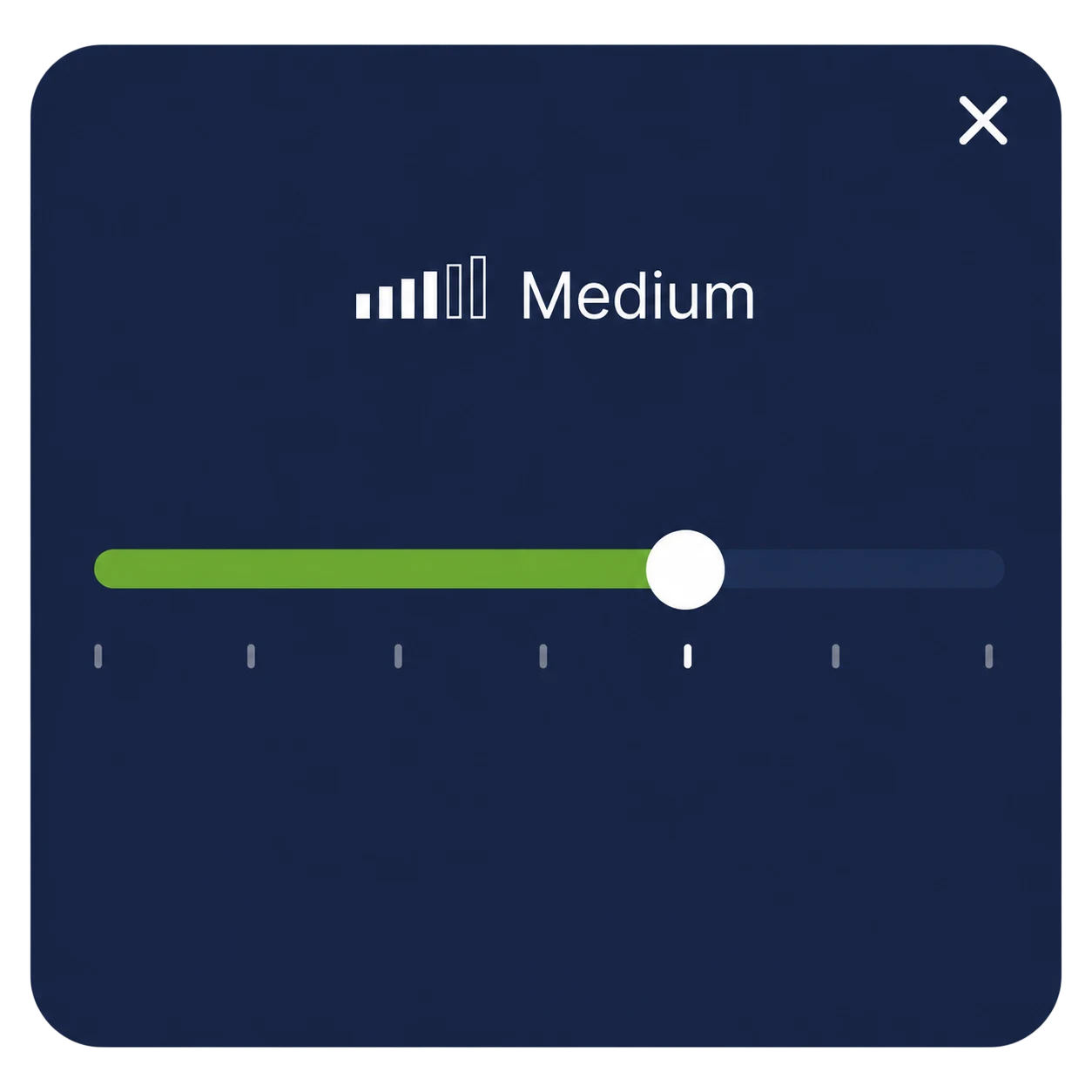
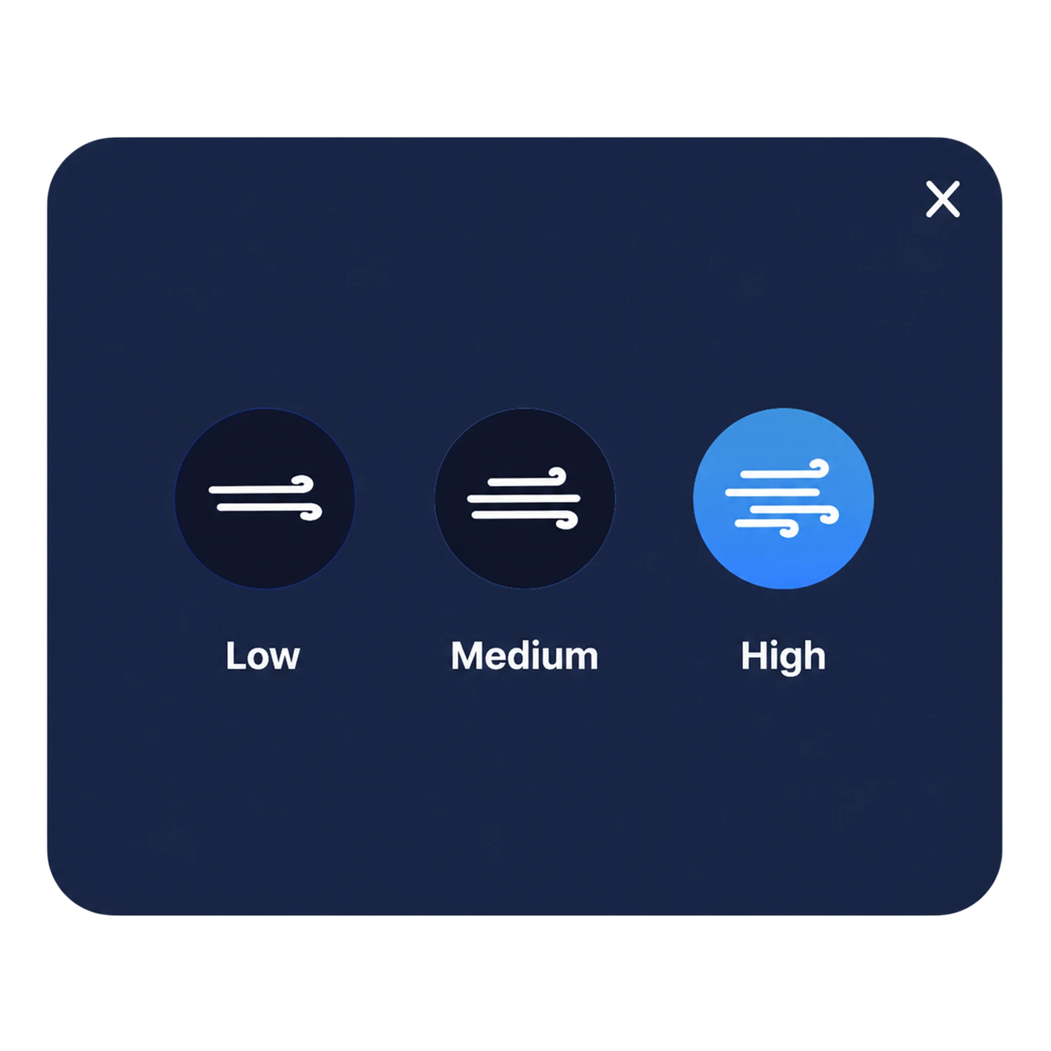
Fragrance intensity icon Fragrance intensity selection interface

Set the fragrance intensity. Compatible single-channel equipment supports low and high output levels.

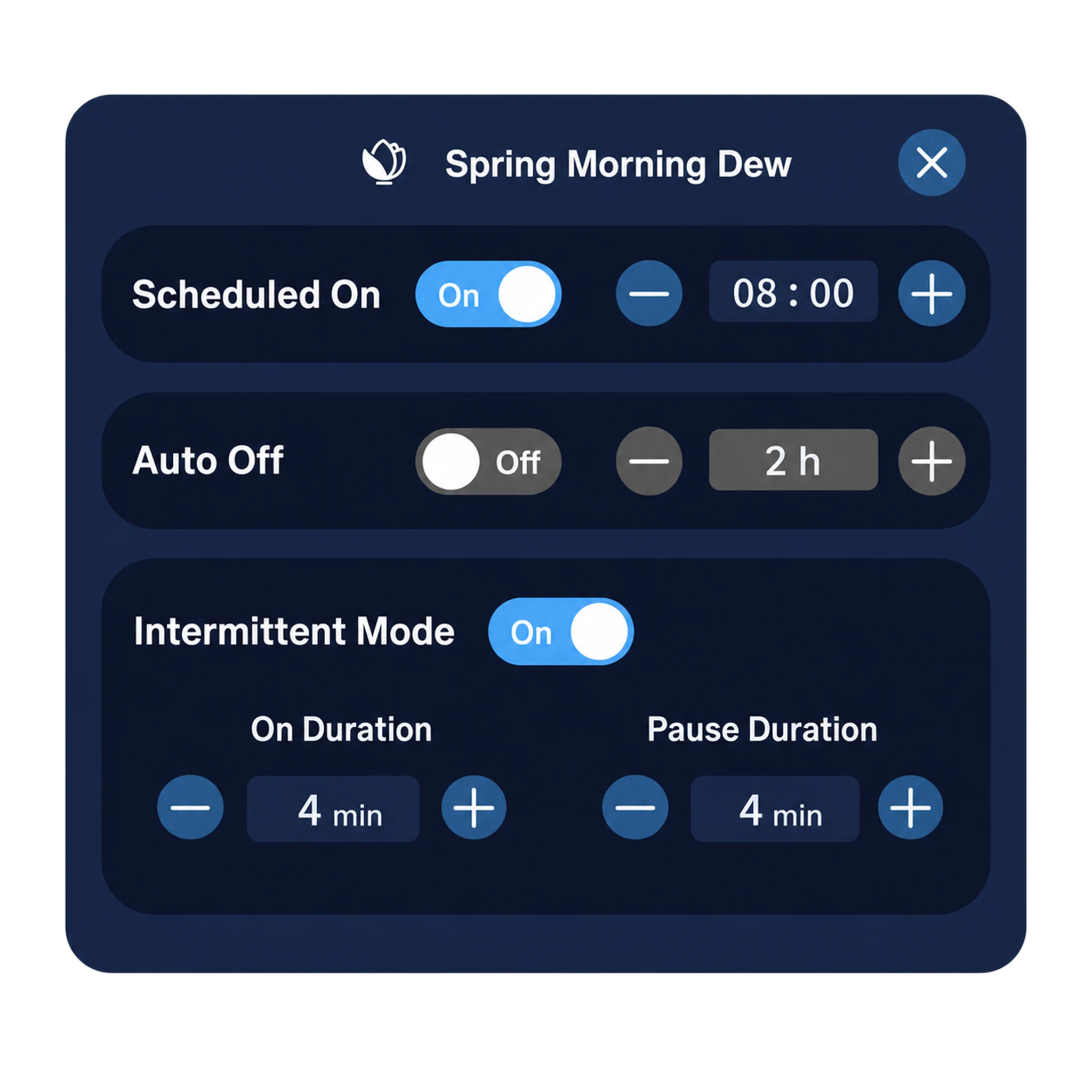
Fragrance schedule icon Fragrance timing and intermittent operation settings interface

Schedule the start time, set the operating duration for automatic shutdown, and configure the fragrance release and pause cycle for intermittent operation.

Explore Our Whole-Home Smart Fragrance Products

Engineering Configuration

Engineering Configuration is used to set device parameters and commission the controller’s RS485 network. It includes master and secondary controller panel configuration, device address assignment, zone binding and motorized air-valve zero-position calibration. This area is intended exclusively for qualified commissioning engineers and requires password verification.

Open Engineering Configuration to access detailed parameter settings. After zone air-valve configuration has been enabled, the master controller can display the opening of each motorized valve and the zone-binding list for supply-air and return-air distribution boxes. If no zone name appears in the list, the valve is not assigned to a zone and does not participate in airflow distribution.

Engineering configuration main interface
Supply-air motorized valve opening configuration interface
Return-air motorized valve opening configuration interface

If the complete list is not visible, swipe up or down to view the remaining items.

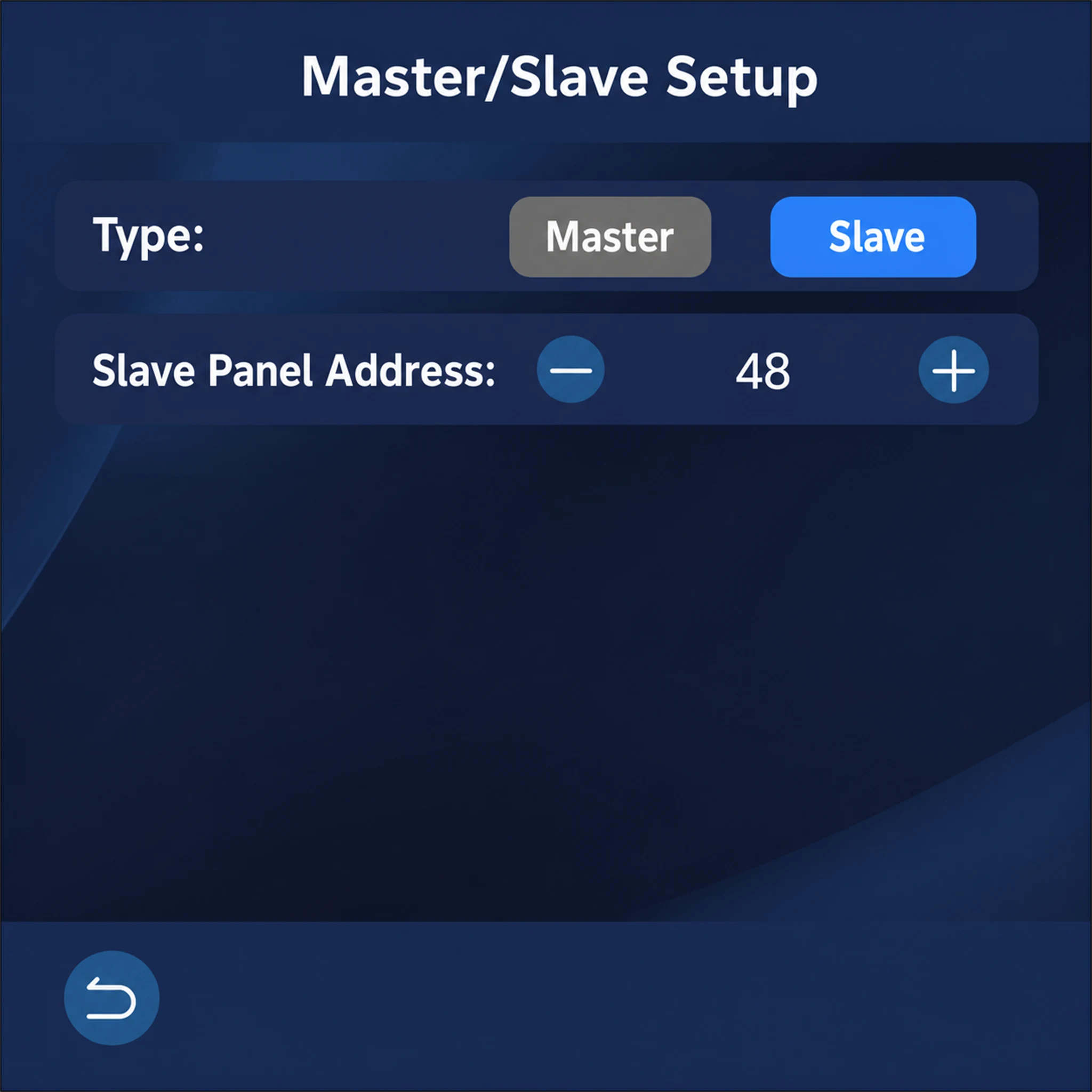
Master/Slave Setup

Select Master/Secondary Setup from Engineering Configuration to define the controller role and assign its network address.

MasterSet this controller as the master control panel and enter the number n of secondary control panels connected to it. The master then recognizes secondary-panel addresses from 48 through 47+n.

SlaveSet this controller as a secondary control panel and assign its address within the range 48 through 47+n. The corresponding panels are identified as Secondary Panel 1 through Secondary Panel n.

Engineering configuration menu interface
Master controller setup interface
Secondary controller setup interface

Recommended configuration order: Master/Secondary Setup → Local Controlled Devices → Zone Configuration (Zone Configuration → Supply-Air Motorized Distribution Box → Supply-Air Motorized Valve Setup).

Local Control Devices

Local Controlled Devices defines which fresh-air ventilation, air-conditioning, underfloor heating and fragrance equipment can be controlled from this panel. The selected configuration determines whether the corresponding function pages appear on the home interface.

Local controlled devices engineering configuration interface

Zone Smart Control Set Up

Zone Configuration is used to enable or disable individual zones, assign zone names and associate each zone with its controller panel.

After a motorized air distribution box is enabled, its connected air valves can be assigned to the corresponding terminal zones or left unassigned. The opening percentage of each valve can also be configured under standard operating conditions. The setup procedure is the same for supply-air and return-air motorized distribution boxes and their corresponding valves.

Zone smart control configuration interface for supply-air and return-air motorized distribution boxes

Air Distribution Box & Motorized Air Valve Configuration

When an air valve is set to Enabled, bind the terminal zone name for the duct connected to that valve. When it is set to Disabled, neither a zone name nor a valve-opening percentage can be assigned.

The zone-binding list for each air valve displays only the zone names that have been enabled in Zone Configuration.

— indicates that the terminal connected to an enabled valve has not been bound to a zone. The valve configuration becomes valid and its opening can be adjusted only after the zone is assigned.

Zone 9: — indicates that the connected terminal zone is enabled but has not been given a zone name. Correct the zone name and binding before commissioning.

After configuring the motorized valve opening, select New Air Valve Test to open the test screen, start the fresh-air system and verify the valve’s operation. Save the configuration for the new opening values to take effect.

Supply-air motorized distribution box valve enablement and zone configuration interface
Supply-air motorized valve zone-binding interface
Supply-air motorized valve opening-percentage configuration interface
New air valve test interface with fresh-air speed selection

WHY CHOOSE US

Why Choose MAXMAC: Pioneer in Integrated Sensor Thermostat Manufacturing

Backed by in-house engineering, testing and manufacturing capabilities, MAXMAC goes beyond the limits of conventional HVAC controllers. Integrating multi-in-one air quality sensing—including PM2.5, CO₂, TVOC, temperature and humidity—directly into a thermostat control board is not a simple matter of combining modules. It requires deep technical expertise and proven manufacturing capability. These two core advantages make MAXMAC a preferred smart thermostat partner for global OEM and ODM customers.

01

Deep Gas & IAQ Sensing Expertise

We do not simply purchase sensor assemblies and combine them with a controller. Years of in-house gas-sensor development have given MAXMAC a strong Sensor DNA. From optical NDIR algorithms and MOS semiconductor processes to complex temperature and humidity compensation, our engineers understand sensing technology at its foundation. This expertise allows us to integrate sensor circuitry closely with the thermostat main control board, address signal interference and thermal drift, and create an elegant modern thermostat that delivers accurate, stable air quality measurements over the long term.

02

In-House SMT & Rapid PCB Prototyping

Our in-house SMT production lines and engineering R&D team support the complete process from PCB design and interface customization to structural development. For individualized B2B OEM and ODM requirements, we provide rapid prototyping and efficient sample iteration. A fully controlled manufacturing chain gives us the flexibility to support both small pilot runs and high-volume delivery while offering cost-effective WiFi thermostat solutions that help customers significantly shorten time to market.

03

Flexible Thermostat Production with Full MES Traceability

MAXMAC combines automated production lines with manual assembly lines, allowing us to switch production methods flexibly according to thermostat structure, order volume and customer-specific requirements. This approach provides an efficient solution for thermostat manufacturing. Automated equipment safeguards consistency and delivery efficiency in volume production, while manual workstations support complex assembly, small-batch pilot runs and customized thermostat manufacturing.

At the same time, every production stage is connected to our MES system, enabling full MES traceability across material batches, PCB assembly, firmware programming, sensor calibration and finished thermostat inspection. This complete data trail gives customers more dependable quality-management assurance and supports reliable OEM/ODM thermostat volume delivery.

TESTING & VALIDATION

CNAS-Accredited Laboratory

MAXMAC’s CNAS-accredited laboratory brings product verification closer to our engineering and manufacturing teams, significantly shortening validation cycles and accelerating the transition from design to volume production. By identifying design weaknesses, potential failure modes, and risk-control points at an early stage, our laboratory capabilities help prevent issues before they reach customers or enter mass production.

Comprehensive mechanical, electrical, environmental, gas, and microbiological testing enables us to verify product performance under demanding operating conditions. This evidence-based validation process strengthens product stability, long-term reliability, and quality consistency while giving OEM/ODM customers greater confidence throughout development and delivery.

CNAS accreditation logo

Specialized Laboratory Facilities

  • Mechanical Reliability Testing Laboratory
  • Electrical Performance Testing Laboratory
  • Bacterial Culture Laboratory
  • Microbiological Testing Laboratory
  • Gas Testing Laboratory
  • Microbiological Inspection Laboratory
  • Balance Room
  • Precision Instrument Room
  • Ventilation Ducts Room
  • High Temperature Testing Laboratory
  • Product Aging Testing Laboratory
  • Impact Testing Laboratory
  • Salt Spray Testing Laboratory
  • Cold Chamber Laboratory
  • Vibration Testing Laboratory
Explore Our CNAS Laboratory
QUALIFICATION CERTIFICATES

Certifications and Quality Management

As a professional manufacturer of thermostats and HVAC controllers, our products come with a wide range of certifications and test reports to ensure quality, safety, and performance. These include ISO 14001, ISO 45001, ISO 9001, IATF 16949, CNAS laboratory accreditation, and more. These certifications reflect our commitment to delivering reliable thermostat and HVAC control solutions that meet global standards.

ISO 14001 Certificate
ISO 45001 Certificate
ISO 9001 Certificate
IATF 16949 Certificate
CNAS Laboratory Accreditation
CNAS Laboratory Accreditation Certificate

TRUSTED PARTNERS

Trusted Customers

MAXMAC supports established HVAC, thermal-management and building-technology companies with integrated sensing, thermostat controller development and OEM/ODM manufacturing services.

From product definition and PCB engineering to validation and volume delivery, our teams work closely with customers to bring reliable, connected climate-control products to market.

HVAC Brands Thermal Management OEM/ODM Partners
Carrier logo Valeo logo DENSO logo Hisense logo Honeywell logo HITACHI logo Panasonic logo YENOVA logo Habit@ logo MAHLE logo
FAQS

Frequently Asked Questions About Programmable Thermostats

How do programmable thermostats work?

Programmable thermostats use schedules, target temperatures, current environmental data and equipment status to determine when connected heating or cooling systems should start, stop or change operating modes. Available control logic depends on the thermostat model and approved project configuration.

Do programmable thermostats save money?

Programmable thermostats can help reduce energy costs, but actual savings depend on the building, connected equipment, climate and temperature schedule. Appropriate programming can reduce unnecessary operation during unoccupied or low-demand periods.

Are programmable thermostats more energy efficient?

Programmable thermostats generally make energy-efficient operation easier than purely manual controls because scheduled temperature changes can prevent connected equipment from running unnecessarily for extended periods. Actual efficiency improvements depend on correct installation, system compatibility and suitable programming.

Programmable vs. non-programmable thermostats: which should I choose?

Choose a programmable thermostat when the project requires scheduled operation, remote control, multi-sensor monitoring or coordination between multiple HVAC systems. A non-programmable thermostat is more suitable when only basic manual on/off and temperature adjustment are required.

What is the Minimum Order Quantity (MOQ) for B2B procurement?

Our standard Minimum Order Quantity for B2B programmable thermostat procurement and volume orders is 1,000 units. Final MOQ, pricing and production lead time are confirmed according to the selected specifications, customization scope and order quantity.

Can we order programmable thermostat samples before bulk production?

Yes. Sample units can be supplied for engineering evaluation, functional testing and project approval before volume production. Sample availability, configuration, cost and preparation time depend on the selected model and required customization.

Does MAXMAC support OEM/ODM customization for bulk orders?

Yes. MAXMAC provides OEM/ODM customization for B2B bulk orders and private-label projects. Available options include enclosure colors, logo printing, user-interface design, sensor configurations, WiFi, RS485 and Modbus communication, software control logic, packaging and labeling. Our engineering team can evaluate project requirements and develop a customized programmable thermostat platform for volume production.

What information is required for a programmable thermostat project evaluation?
  1. Application type
  2. Controlled HVAC equipment
  3. Power supply and voltage
  4. Control interface
  5. Communication protocol
  6. Required sensors
  7. Screen size
  8. Installation method
  9. Target certifications
  10. Estimated order quantity
  11. OEM/ODM customization requirements

Provide Your Details for Professional Product Consultation

Our product experts will provide the most suitable air solutions and product recommendations.