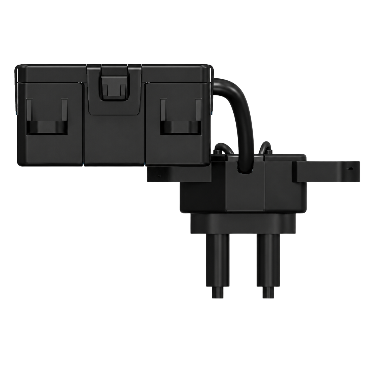
Planning an installation? Explore MAXMAC integrated, remote-emitter and dual-emitter solutions for your duct layout.
1. Choose the Right Emitter Configuration
In automotive OEM applications, negative-ion modules are typically installed upstream of an HVAC outlet. Because the ions must be carried by moving air into the cabin to support air purification, the discharge position needs to couple effectively with the outlet airflow. The industry challenge is that duct geometry and available mounting locations vary from one vehicle HVAC design to another. To address this packaging challenge, MAXMAC offers the following three integration approaches.
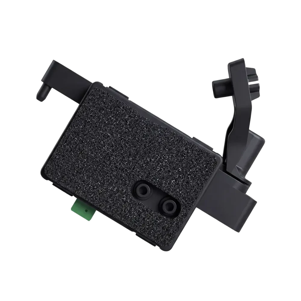
Integrated Emitter
The carbon-brush emitter and module body remain together. This is compact and minimizes separate high-voltage routing when the complete module can be mounted close to the target air stream.
Check More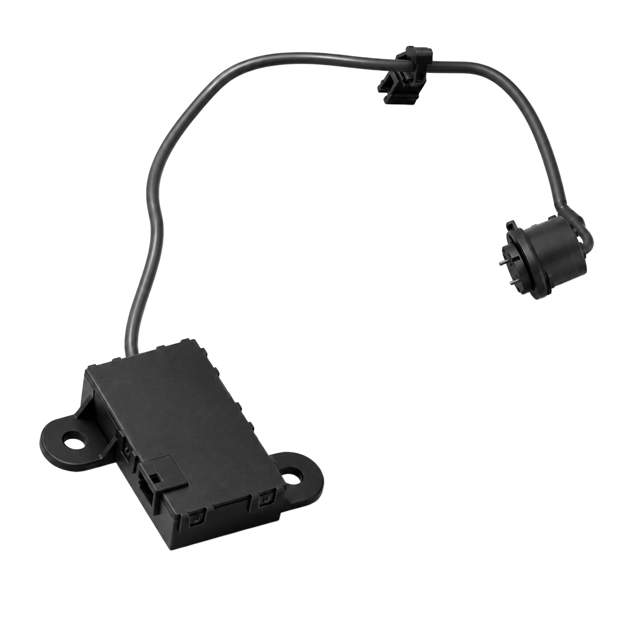
Single Remote Emitter
One extended discharge head reaches a narrow, curved or irregular duct while the larger module body stays in an accessible protected mounting area.
Check More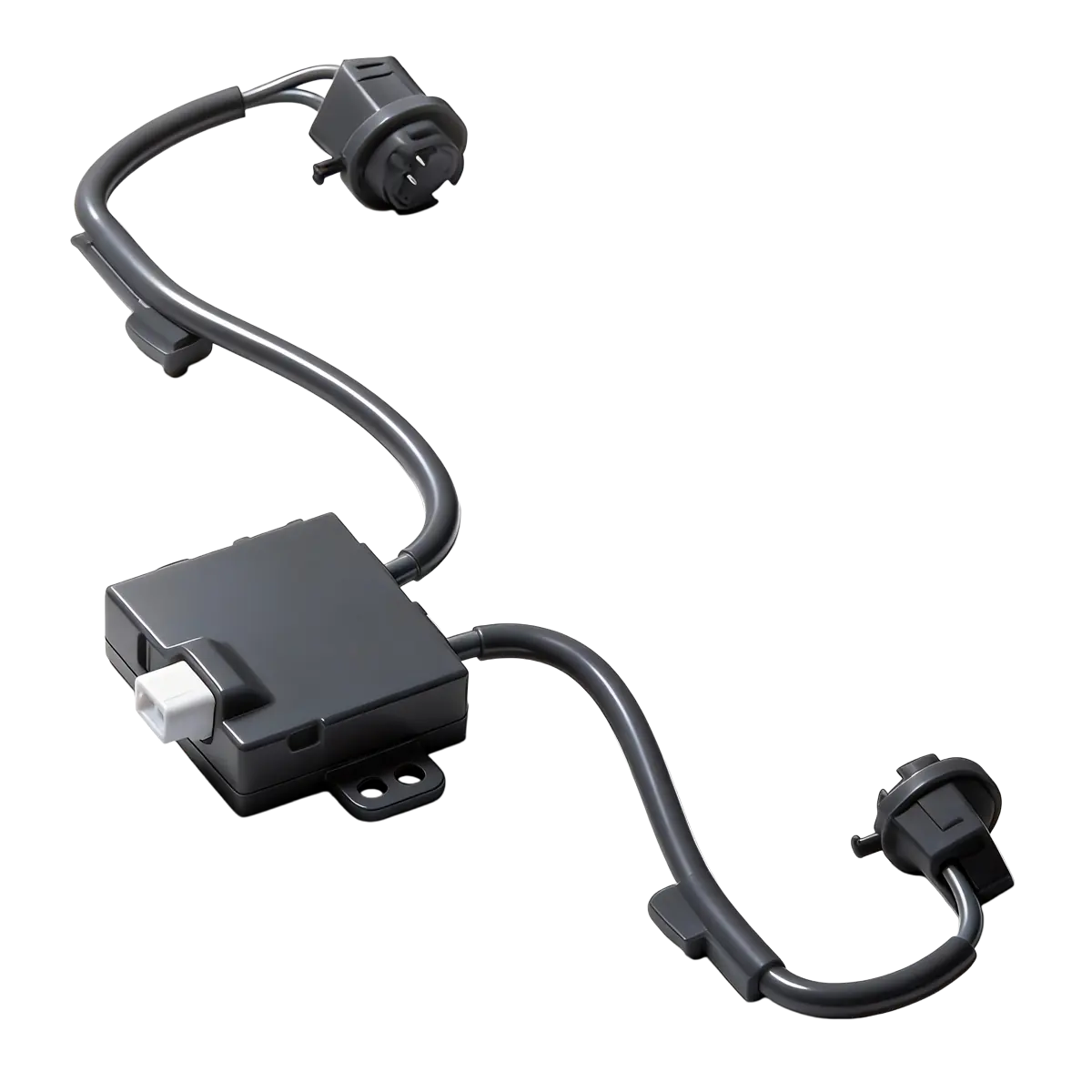
Dual Remote Emitters
Two release points can serve separate branches or outlet zones. This can broaden distribution coverage, but the installed system must establish the actual concentration in each zone.
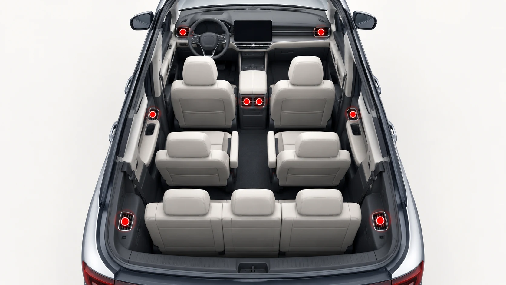
Check MoreMultiple negative-ion modules are typically distributed throughout a cabin near both front and rear HVAC outlets to support more even air-treatment coverage.
- Sedan: Cover the front dashboard outlets and rear center-console outlets.
- SUV: Cover front and rear outlets; longer cabins or additional climate zones may require more modules.
- MPV: Cover front, middle and rear climate zones, scaling the module count to the number of rows and outlet layout.
Vehicle type mainly changes the required number of modules and discharge points. Front and rear airflow paths should be included in every layout so that ion delivery can be validated throughout the occupied cabin.
2. Place the Emitter in the HVAC Airflow
The emitter should release ions into useful moving air rather than into a stagnant cavity. A downstream location near an outlet can shorten the path between emission and cabin delivery, while the airflow carries ions through the grille. The illustration below shows an integrated module positioned beside the outlet with the discharge end exposed to the stream and clear of the duct wall.
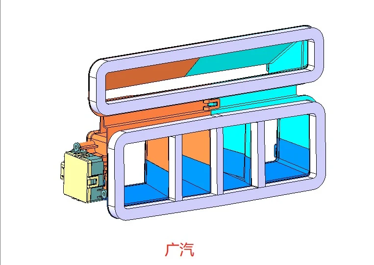
This standard duct geometry is ideal for an integrated ion module. The emitter sits directly in the outlet airflow, providing effective ion delivery with fewer parts and lower material cost.
Position the emitter so the brush remains exposed to the main airflow. Maintain clearance from conductive surfaces and condensate paths, and confirm that HVAC doors, vanes and actuators retain full travel. Avoid recessed pockets where recirculating air can weaken ion transport.
3. Mechanical Packaging for Straight and Irregular Ducts
Integrated modules work well when the mounting point aligns with the target airflow. Where usable airflow and mounting space do not coincide, a remote emitter lets the main body remain at a secure mounting point while the compact discharge head reaches the duct.
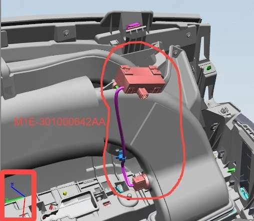
This remote-head design adapts easily to irregular duct geometries. Installation requires only a small opening near the air outlet, while the main module can be mounted in an accessible service location. The flexible extension lead simplifies routing during assembly and supports efficient installation.
A dual-emitter arrangement is especially useful when two outlet positions are close together: one high-voltage module can serve both outlets. This can reduce hardware count and system cost while helping distribute negative ions more evenly, provided performance is confirmed through airflow mapping and installed-system testing. Dual remote emitters place one release point in each airflow branch. Since branch airflow may differ, verify ion concentration at both outlets over the intended blower range.
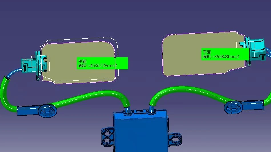
Mount the module at its defined retention points and keep the connector accessible. Verify discharge-head clearance under vibration and tolerance variation, and protect the emitter from condensation and contamination.
4. Integrate Power, EMC and Grounding
A negative-ion generator converts the vehicle’s low-voltage supply into the high voltage required for ion generation. Input protection and filtering should follow the module specification and the vehicle electrical test plan. Confirm startup behavior and current demand across the intended supply range.
Use a controlled low-voltage return path. Separate the high-voltage lead from antenna, sensor and communication wiring to limit coupling. Confirm conducted and radiated EMC with the complete HVAC assembly.
Explore MAXMAC negative ion generator modules, including the FS11, M30 and M2901.
Next step: Send your duct layout, airflow range and control requirements to our engineering team.