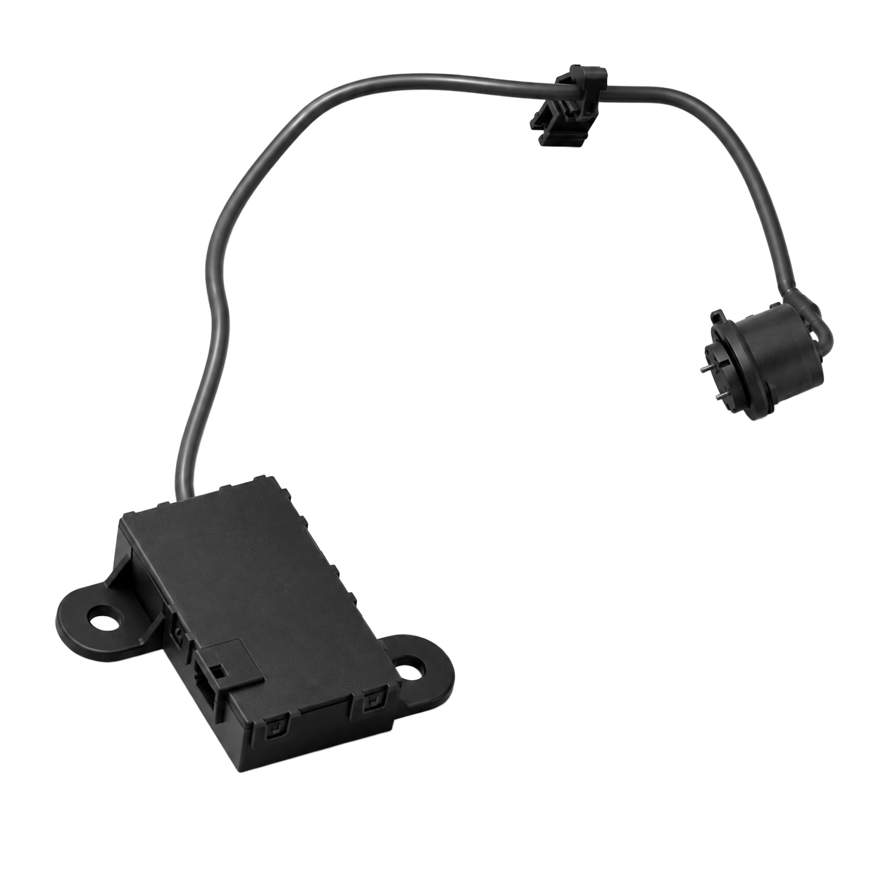
1. Ion Generation and Ozone Share a Discharge Region
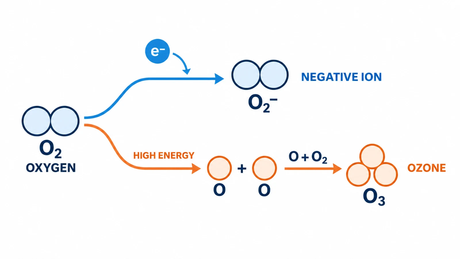
A negative ion generator creates a controlled corona at its emitter. Electrons released near the tip can attach to oxygen molecules. The simplified first step is O2 + e− → O2−. In ordinary air, later reactions can turn this first ion into other oxygen-containing ion clusters.
Ozone follows a different path. More energetic electron collisions can split an oxygen molecule into oxygen atoms. An oxygen atom can then join another oxygen molecule to form O3. The amount formed depends on the discharge state, so useful ion generation and ozone control must be considered together.[1]
A negative ion generator is designed to deliver negative ions. A bipolar plasma ion generator produces both positive and negative ions. The negative-ion reaction below illustrates only one part of a bipolar discharge; it is not a complete model of plasma chemistry. Both designs need ozone control. EPA notes that bipolar ionization can generate ozone and other by-products unless precautions are taken in design and maintenance.[5]
The shared approach is to control the discharge and verify the assembled product. The emitter-tip examples here apply to corona-based ion generators; other plasma discharge structures need their own design assessment.
2. Why a Small Tip Radius Matters
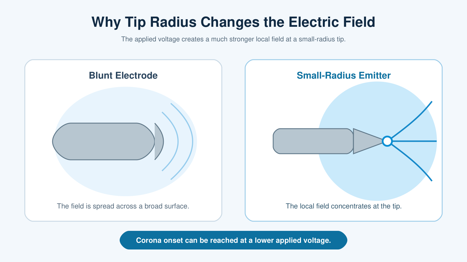
Electric field strength is not uniform around an emitter. It becomes concentrated where the surface is sharply curved. A carbon fiber or fine metal needle uses this effect to create a strong local electric field at its tip. Corona onset can then be reached at a lower applied voltage than it can with a blunt electrode.[2]
This geometry creates room to meet an ion-output target without applying more discharge energy than the task needs. It does not prove the ozone level by itself. The full electrode arrangement and electrical operating point still determine how the discharge behaves.
3. Carbon-Fiber Brushes and Fine Metal Needles
Emitter material matters through the structure it creates at the discharge point. Carbon fiber and metal needles can both provide a small radius, but they organize that point in different ways.
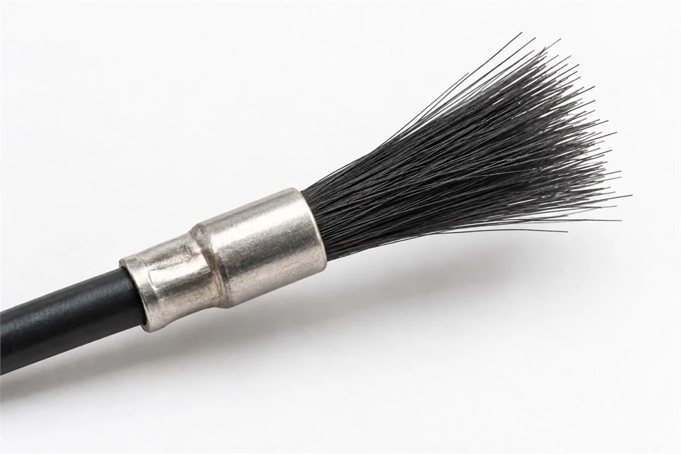
Carbon-Fiber Brush
A fiber bundle provides many microscopic tips. The available emission sites are spread across the brush rather than fixed at one large point. Carbon-brush electrodes have been studied for low-ozone corona devices.[3]
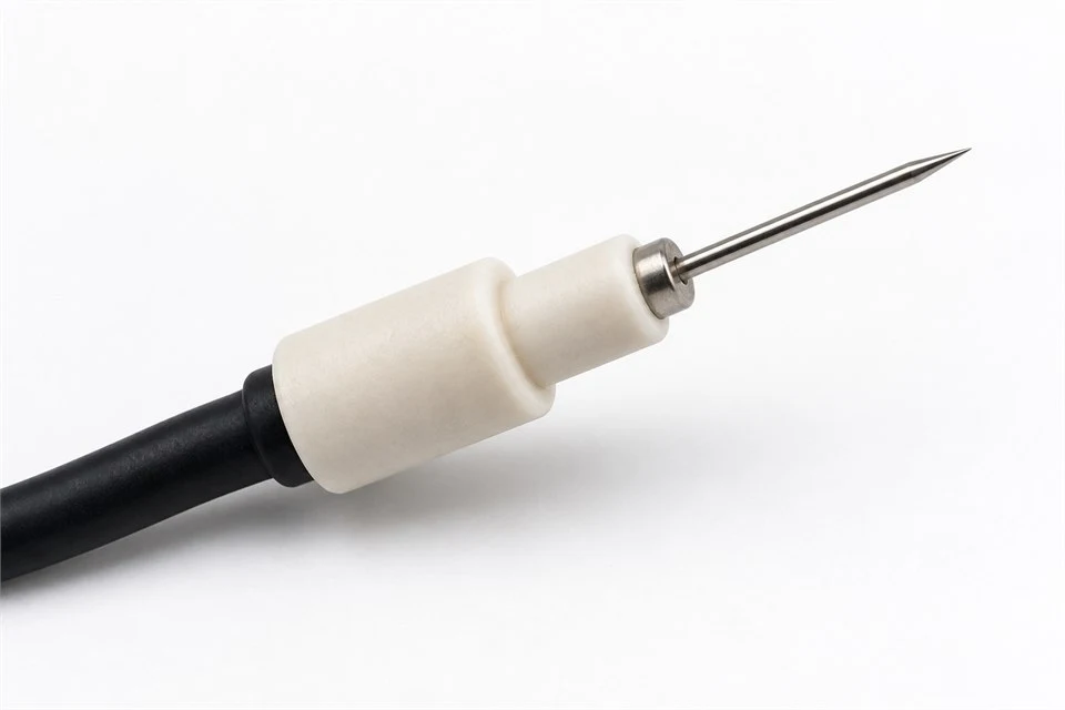
Fine Metal Needle
A shaped needle provides one defined tip. Its position and direction can be controlled precisely during assembly, which helps keep the intended discharge geometry repeatable.
Neither material works independently of its surface condition and circuit. A contaminated brush or damaged needle changes the effective geometry. Assembly tolerances and aging can also shift the discharge point over the product life. Low-ozone design treats the emitter and high-voltage stage as one system.
4. Set the Electrical Operating Window
The tip determines where the field is strongest. The high-voltage circuit determines how strongly the discharge is driven. Their shared operating window must produce the required ion output while keeping the discharge current controlled.
Select a stable operating range that meets the required ion-output target and the measured ozone requirement in the intended configuration.
Increasing voltage can raise ion output, but it can also increase the number and energy of electron collisions. Current control helps keep a sharp emitter within its intended discharge range. The final setting is established through measurement, not from tip geometry alone.
Additional Checks for Bipolar Plasma Generators
For a bipolar module, document both positive and negative outputs, the electrode spacing, drive waveform, current limits and duty cycle. Verify the complete operating configuration rather than transferring a setting from a negative-only module. Balanced ion output is not evidence of low ozone; measure ozone separately.
5. Test the Finished Generator
Material selection shows design intent. A finished-generator test shows the combined result of the emitter, circuit and assembled structure. The chamber background is measured first, the generator is operated for a defined period, and the air is measured again using the same method.
Record the sample model, supply voltage, operating mode, airflow, sampling position, temperature, humidity, chamber volume and test duration. Include the measurement method and reporting limit. For an OEM project, agree which operating modes, airflow conditions and aged or contaminated emitter conditions need evaluation. Verify the installed system as well as the module when the enclosure or air path changes the test configuration.
Define the Ozone Criterion Before Testing
Select the applicable product and market requirements with the testing laboratory. UL Solutions describes its UL 2998 zero-ozone emissions validation criterion as below 0.005 ppm (5 ppb). This is a defined validation procedure, not a claim of absolute absence of ozone.[6] A concentration from a different chamber procedure does not by itself establish UL 2998 validation. Ozone testing also does not replace electrical safety assessment or evaluation of other by-products.
The photograph and readings below illustrate the negative ion generator test case in section 6.
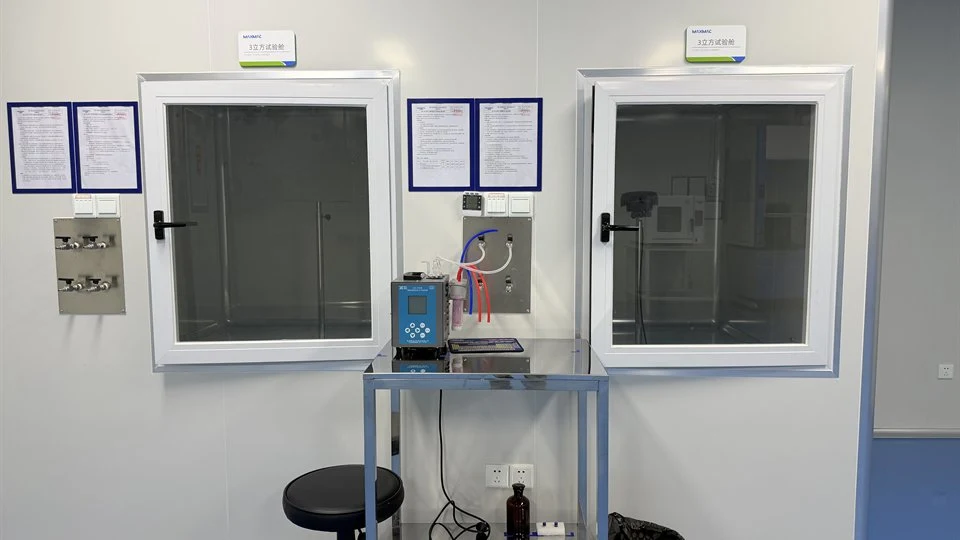
- Measure the chamber backgroundBackground value: <0.003 mg/m3
- Operate the generator for 1 hourThe complete unit remains powered.
- Measure ozone againOperating result: <0.003 mg/m3
6. Negative Ion Generator: Third-Party Test Case
One negative ion generator was evaluated in a 3 m3 chamber. After the environmental background was established, the sample was powered for one hour. Both the background and powered-operation result were reported as <0.003 mg/m3 under these test conditions.
| Test item | Condition or result |
|---|---|
| Sample | Negative Ion Generator |
| Chamber volume | 3 m3 |
| Background stabilization | 1 hour |
| Powered operation | 1 hour |
| Test method | HJ 590-2010 ultraviolet photometric method |
| Background value | <0.003 mg/m3 |
| Operating result | <0.003 mg/m3 |
The less-than sign is important. It means the measured concentration was below the laboratory’s reported value; it does not establish an absolute absence of ozone. The result applies to this sample and the stated procedure. It is not a test result for the B02, M1801 or M96 plasma generators, and it does not establish certification or validation for those products. Obtain a report for the selected model and configuration. HJ 590-2010 defines an ultraviolet photometric method for measuring ozone in ambient air.[4] The linked English document is a reference translation; the signed Chinese test report is the controlling source.
View the English Reference Translation7. What Low-Ozone Design Means
A small-radius emitter concentrates the field. A matched high-voltage circuit holds the corona within its intended operating range. A finished-product test confirms the ozone level produced by that combination. These three parts form one engineering method rather than three separate product claims.
Next step: Review MAXMAC negative ion generator modules, explore bipolar plasma generator modules, or discuss a project-specific ozone requirement.
References
- Jenkins et al., Prodigious Amounts of Hydrogen Oxides Generated by Corona Discharges on Tree Leaves, Journal of Geophysical Research: Atmospheres, 2022.
- Weng et al., Pilot Study on the Production of Negative Oxygen Ions Based on Lower Voltage Ionization Method and Application in Air Purification, Atmosphere, 2024.
- Development of Low Ozone Electrostatic Precipitator using Carbon Brush Electrode, IEEJ Transactions on Fundamentals and Materials, 2021.
- Ministry of Ecology and Environment of China, HJ 590-2010: Ambient Air—Determination of Ozone—Ultraviolet Photometric Method.
- US EPA, Bipolar Ionization in Portable and In-Duct Air Cleaners.
- UL Solutions, Zero Ozone Emissions Validation.