1. Negative Ions Are Present Throughout Nature
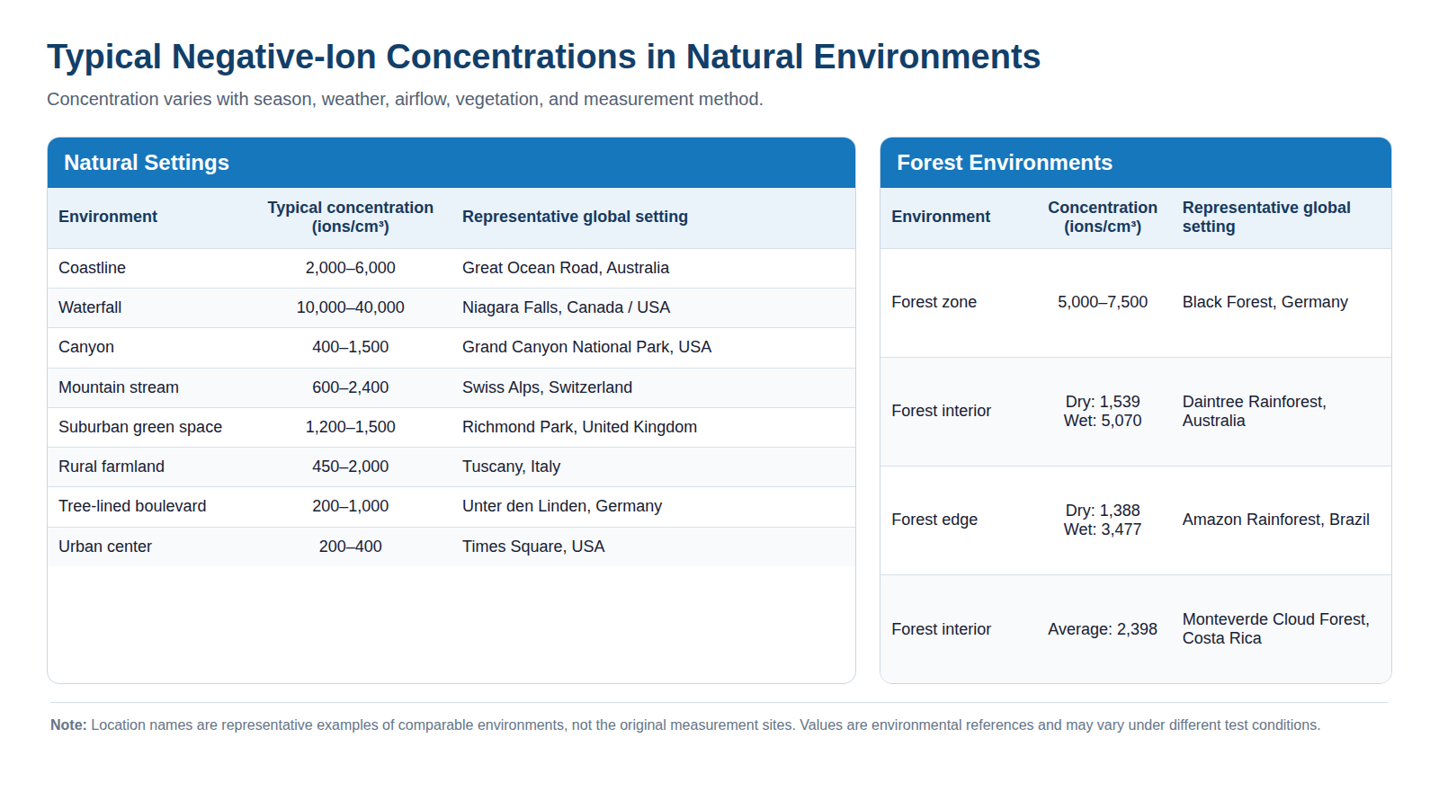
Negative ions are not limited to engineered air-treatment equipment; they occur naturally all around us. Their measured concentration can change significantly with the environment, season, weather, airflow, and measurement method. The chart below shows this variation across different natural settings. The individual locations are not the focus here—the key point is that ion concentration is not a fixed value and must always be considered together with its measurement conditions.
2. How Does a Negative Ion Generator Work?
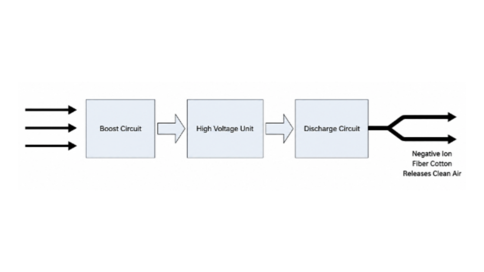
A negative ion generator uses pulses and an oscillator to boost a low voltage to a high negative DC voltage. The high DC voltage at the tip of the carbon brush creates a strong corona discharge, rapidly releasing a large number of electrons. Because free electrons cannot remain in air for long, they are immediately captured by oxygen molecules (O2) and form negative oxygen ions. Under the influence of the negative electric field, these ions diffuse into the surrounding airflow, while positive ions are attracted toward the high-voltage negative field and neutralized.
From an electrical viewpoint, the process can be read as a simple chain: the 12 V supply enters a boost circuit, passes through the high-voltage unit, and reaches the discharge circuit connected to the carbon-brush emitter. Stable ion output therefore depends on both high-voltage conversion and the mechanical relationship between the emitter and the moving air.
3. How Negative Ions Affect Airborne Particles
Negative ions attach to positively charged smoke and dust particles suspended in air. Once charged or neutralized, fine particles can aggregate into larger clusters or settle onto nearby surfaces. In a system that also contains a filter, this behavior can make some airborne material easier for the filter to capture as air recirculates.
A negative ion module should therefore be evaluated as part of the complete airflow and filtration path. Its effect depends on emitter position, ion transport distance, air velocity, filter design, particle loading, surface deposition, and cleaning strategy. It does not replace mechanical filtration, and results measured in one chamber or duct cannot automatically be transferred to a different system layout.
4. Inside a Negative Ion Generator Module
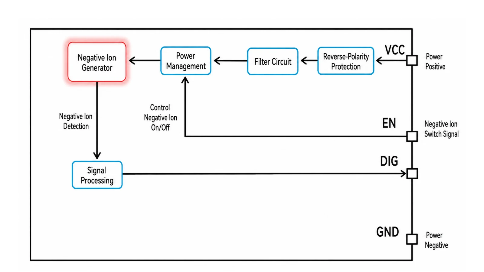
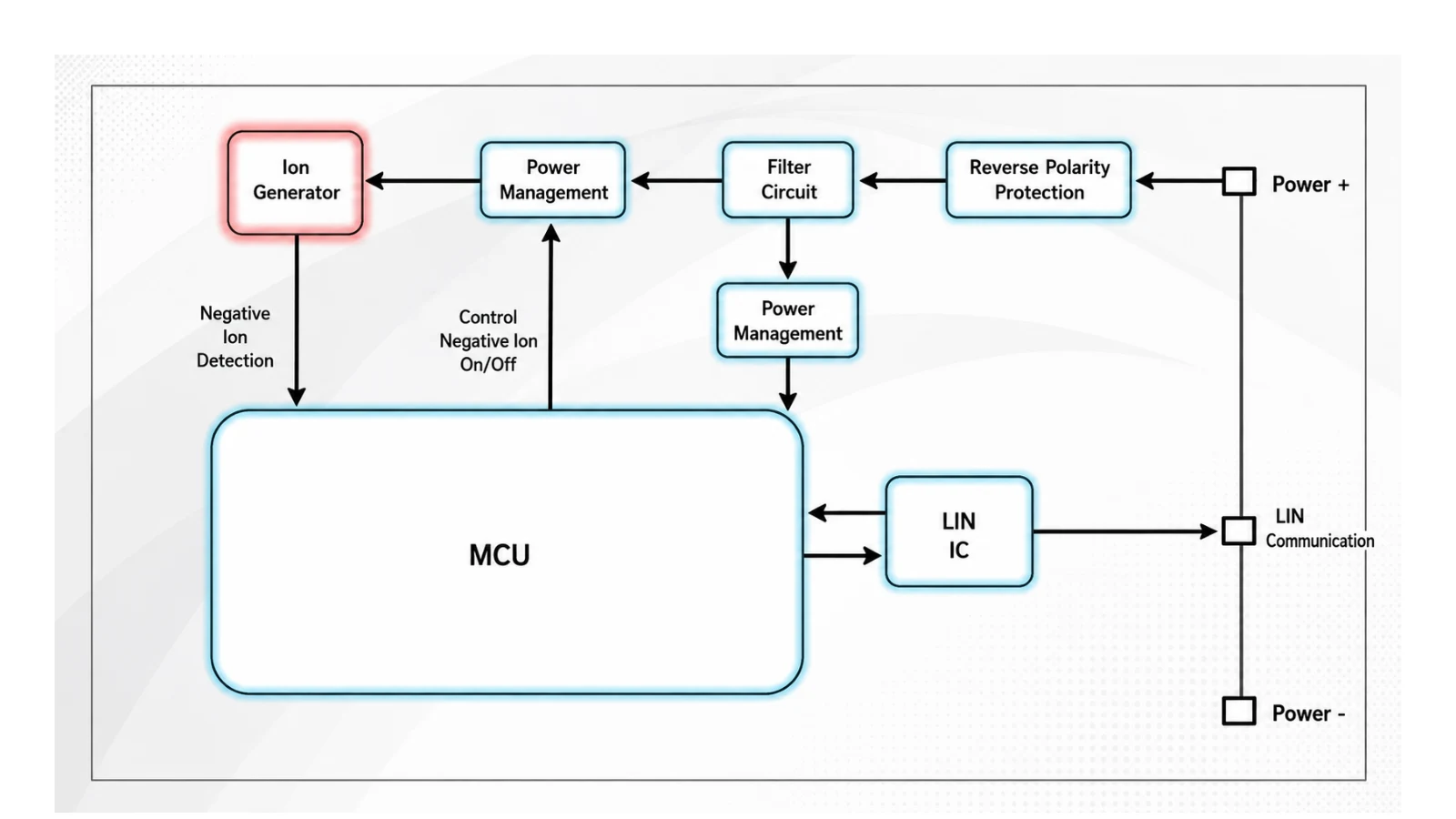
In the electronic block diagram, the positive supply enters through the VCC terminal and first passes through reverse-polarity protection. A filter circuit reduces supply disturbance before power management drives the negative-ion generator. The EN input switches generation on or off. Ion detection is processed by a signal circuit and returned through the DIG terminal as an operating or diagnostic signal, while GND provides the negative supply reference.
This arrangement separates protection, power conversion, ion generation, and feedback into clear functional blocks. It allows the host system to command the module and check its status without exposing the vehicle controller directly to the internal high-voltage discharge stage.
5. Control Interfaces: Hardwired and LIN
A basic implementation can use hardwired EN and DIG signals. A more integrated automotive design adds an MCU and LIN transceiver. In that architecture, the MCU receives ion-detection feedback, controls negative-ion operation through the power-management stage, and exchanges commands and status information with the vehicle controller through the LIN interface.
The software architecture follows the same functional split: boot and driver layers support system, power-management, LIN, and ion-control tasks. The purpose is not to make the high-voltage principle more complex, but to give the vehicle a controlled way to schedule operation, enter low-power states, report status, and coordinate the ion module with HVAC behavior.
6. Key Technical Parameters
The following parameters define this negative-ion module configuration. Confirm the datasheet of the selected module before final design approval, because output, temperature, current, and ozone limits can vary by product.
| Parameter | Specification |
|---|---|
| Rated voltage | 12 V DC |
| Voltage range | 9–16 VDC |
| Operating current | ≤70 mA |
| Standby current | ≤0.1 mA |
| Communication method | LIN communication or hardwired communication |
| Ion concentration | >2 million particles/cm³ at 1 m from the carbon brush, with airflow velocity ≤5 m/s |
| Ozone concentration | <0.045 ppm |
| Operating temperature | −40°C to 85°C |
| Storage temperature | −40°C to 90°C |
7. Installation and Module Configurations
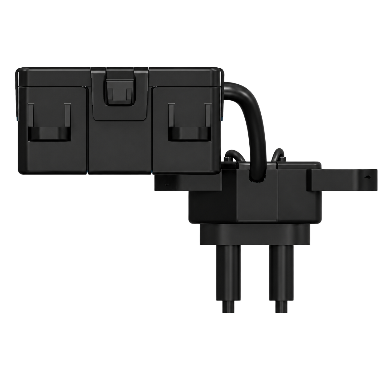
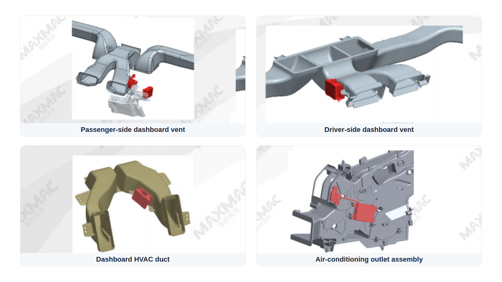
In automotive HVAC applications, the module can be installed at or near dashboard outlets, including driver-side and passenger-side vents. This position uses the duct airflow to carry ions into the cabin. During packaging, engineers must keep the emitter clear of conductive surfaces, protect high-voltage wiring, avoid locations where condensation or contamination can collect, and confirm that the selected airflow produces the required concentration at the specified distance.
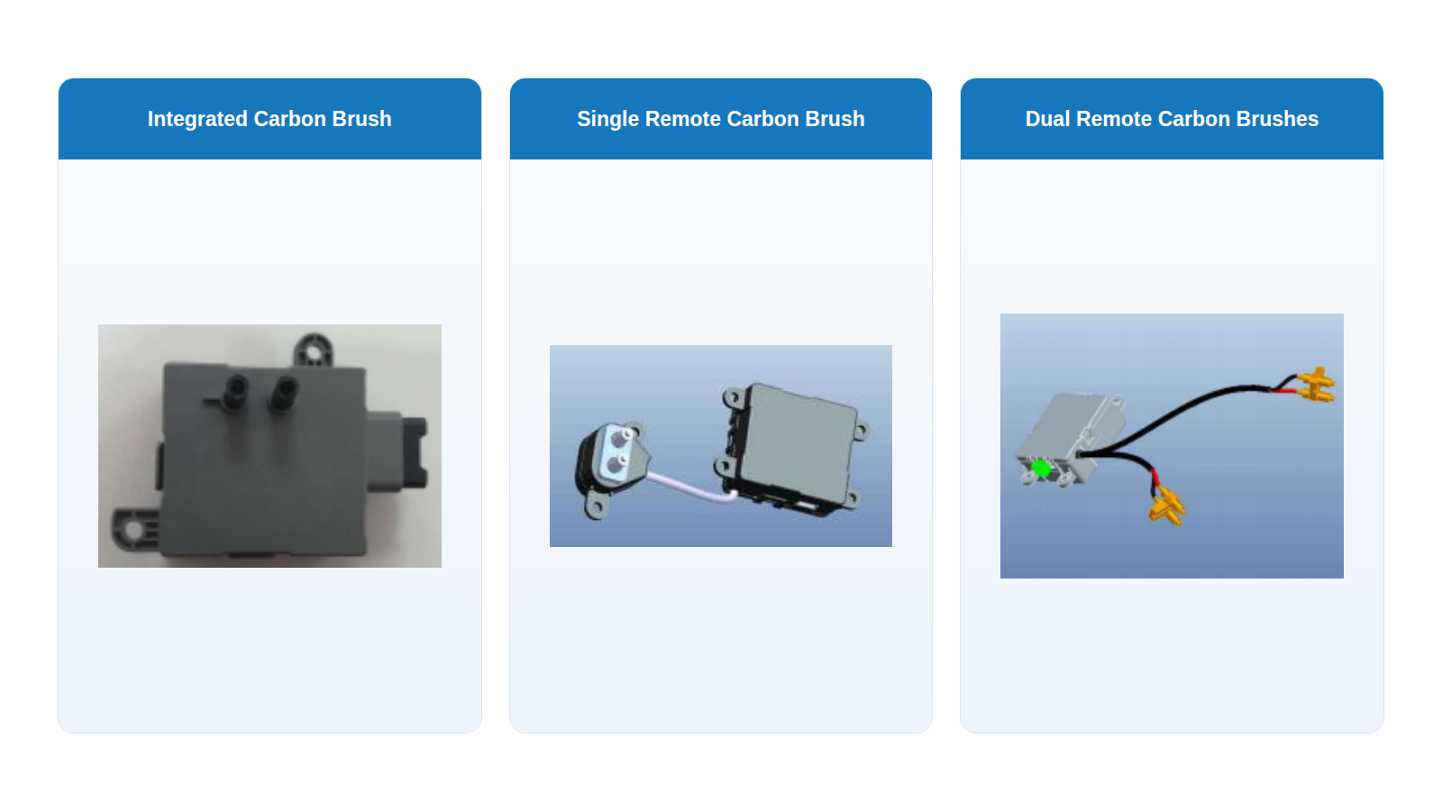
Negative-ion generator modules are available in three mechanical arrangements: a single carbon brush integrated into the module body, a single carbon brush separated from the body, and two remote carbon brushes. An integrated emitter simplifies the assembly, while a remote emitter gives the high-voltage power unit and discharge point more packaging flexibility. A dual-emitter arrangement can distribute the discharge across two airflow locations, subject to the product specification and system validation.
8. Validation and Performance Testing
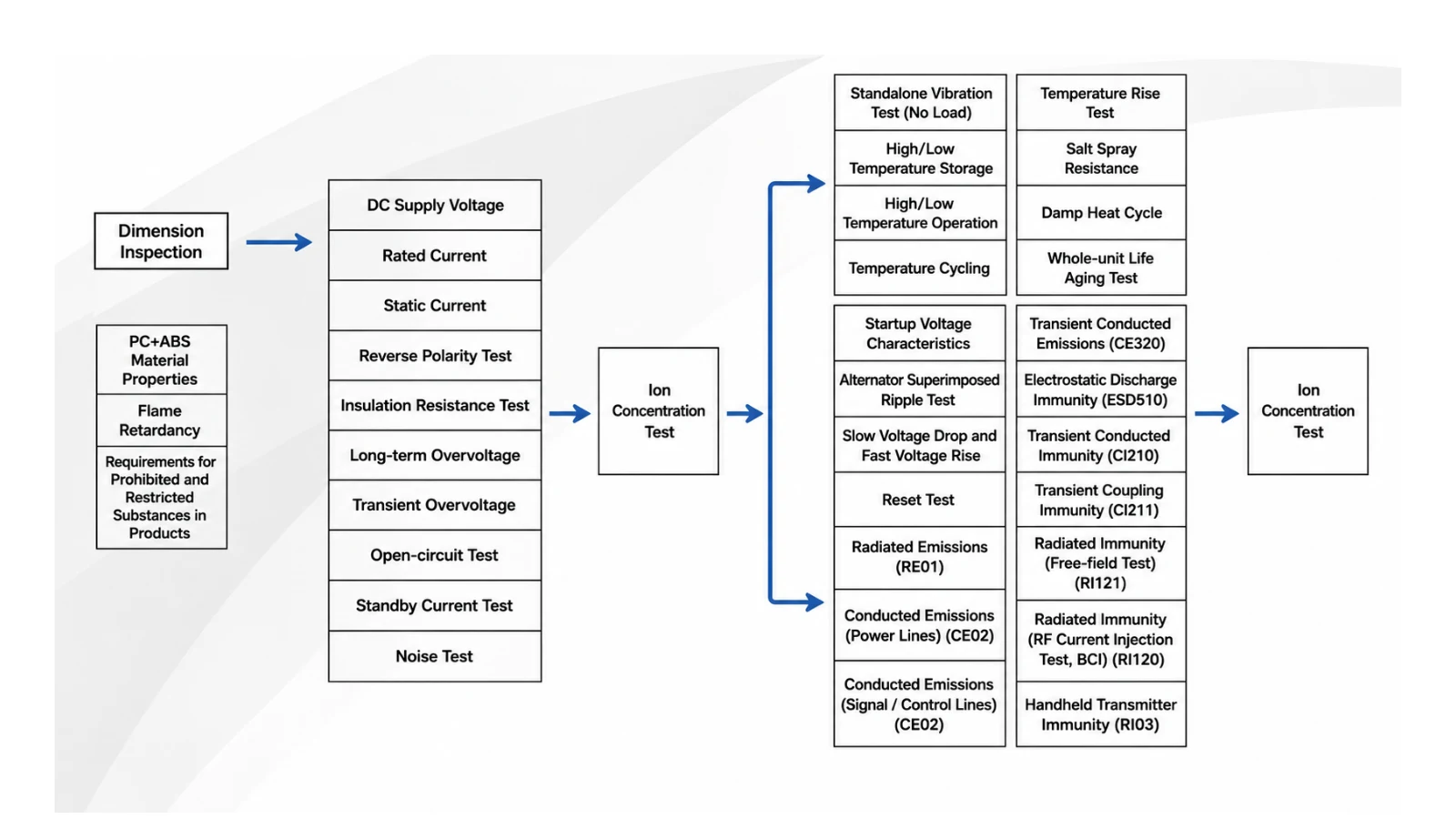
Automotive DVP verification begins with dimensional and material checks, then covers supply voltage, rated and standby current, reverse polarity, insulation resistance, overvoltage, transient conditions, open-circuit behavior, and noise. The flow continues through ion-concentration checks, temperature and humidity exposure, vibration, salt spray, life and cycling tests, plus conducted and radiated EMC verification. The final test items and acceptance limits must be adjusted to each automaker’s standards.
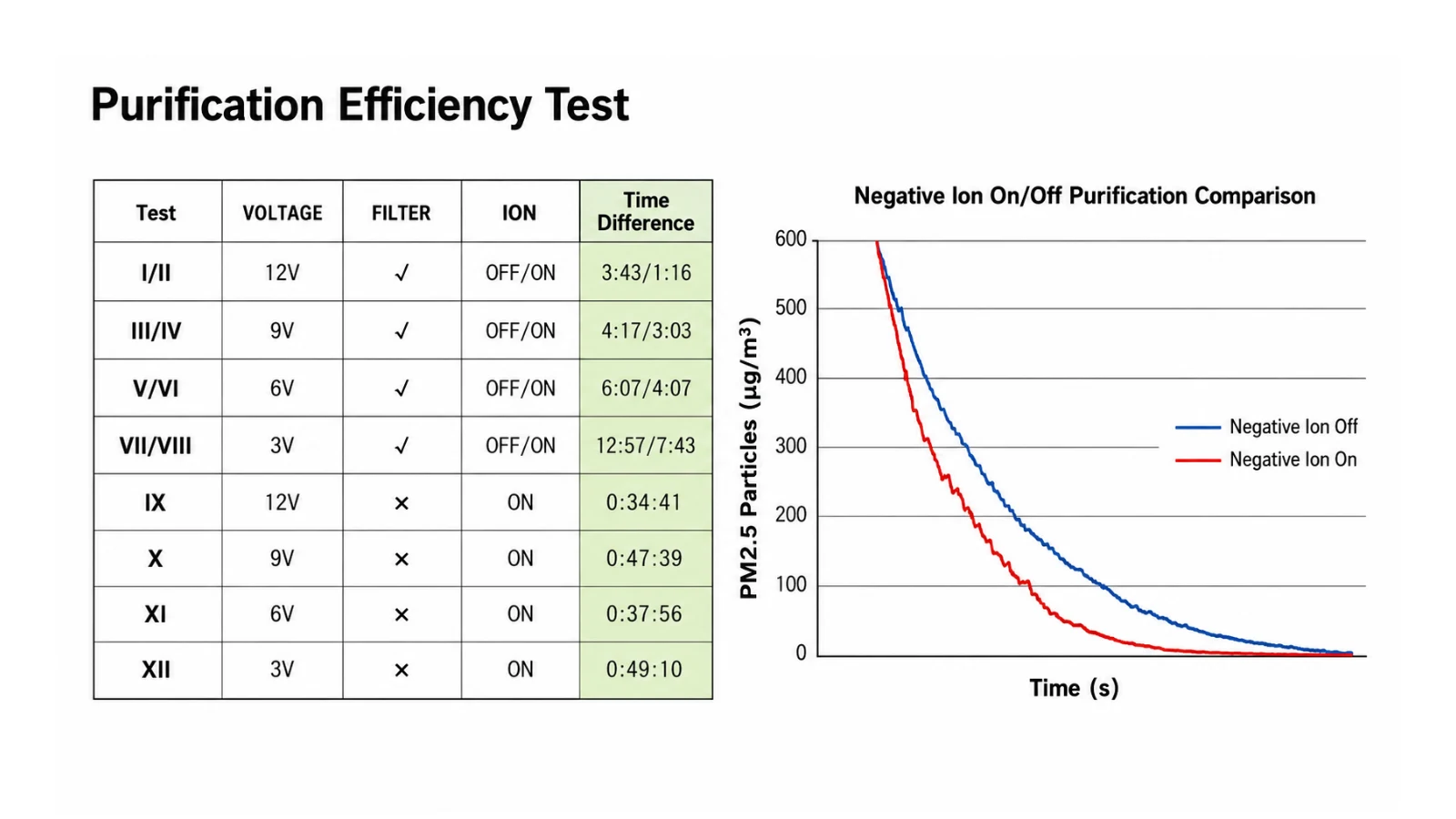
The purification test compares negative-ion OFF and ON conditions while also varying supply voltage and filter configuration. In the plotted comparison, the PM2.5 curve falls more quickly with negative-ion generation switched on. This is useful system-level evidence, but it is not a universal removal-rate claim: chamber geometry, starting concentration, airflow, filter state, emitter placement, voltage, measurement position, and test duration all influence the result.
Selecting a Module for an OEM Project
The working principle is shared across many negative-ion modules, but final product selection must be based on the actual supply range, ion-output test method, ozone limit, brush arrangement, airflow, control interface, environmental range, connector, installation space, and validation standard. Confirm those conditions before comparing headline ion-concentration values.
Explore: MAXMAC negative ion generator modules or contact our engineering team to discuss an application.