Why Temperature Affects Relative Humidity Measurements
Relative humidity is not simply the amount of water vapor in the air. It is the ratio between the actual water-vapor pressure and the saturation vapor pressure at the same temperature. The relationship can be expressed as:
When the actual moisture content remains approximately constant, warmer air has a higher saturation vapor pressure, so its relative humidity falls. This means heat from the product can make a sensor report both an artificially high temperature and an artificially low RH. The effect becomes more pronounced in high-humidity conditions, where a small temperature bias can create a much larger RH shift. In a multi-sensor product, thermal design is therefore part of humidity accuracy, not only temperature accuracy.
Where Heat Comes From in a Multi-Sensor Module
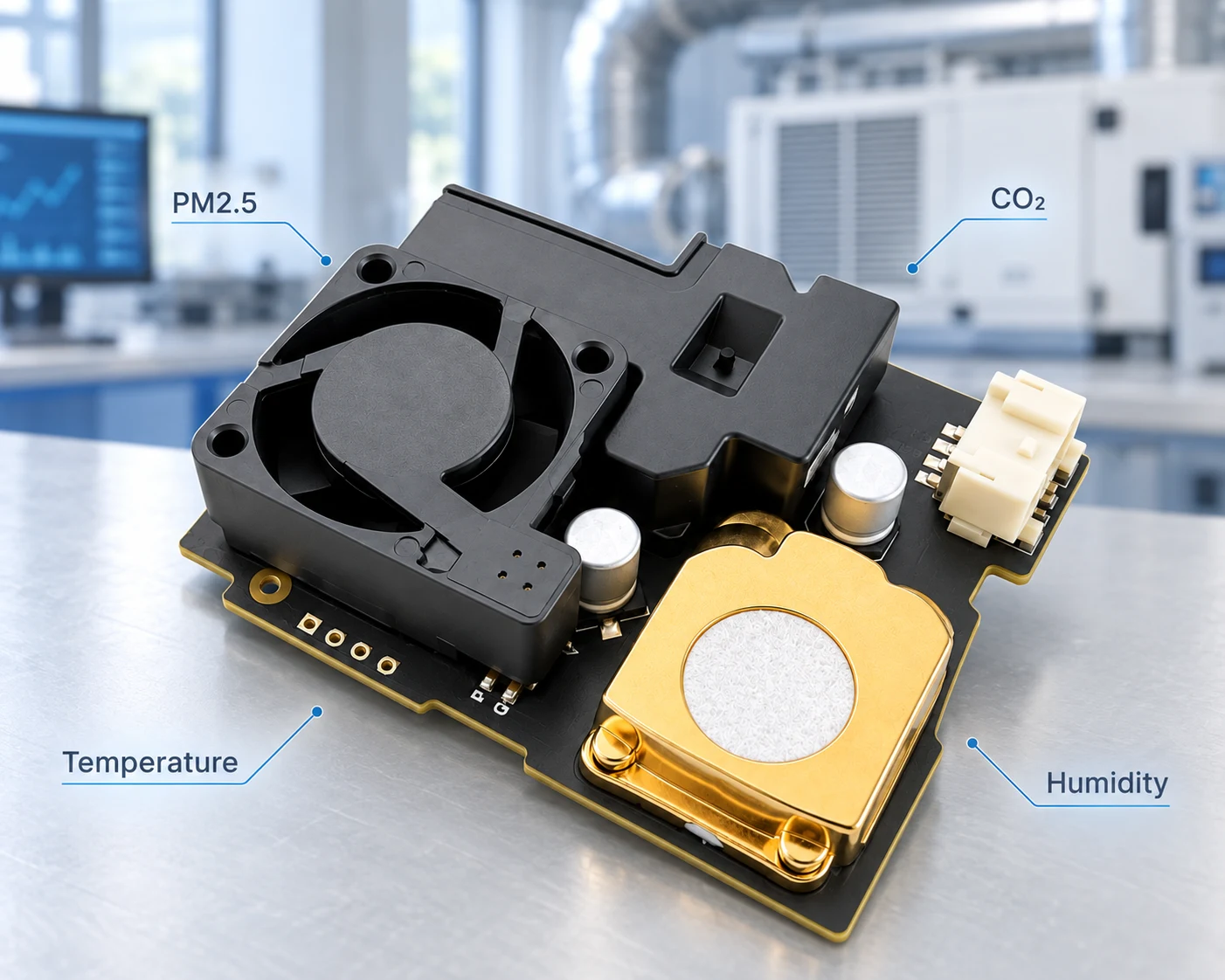
A multi-in-one air-quality module places several measurement principles in a small volume. Each device may meet its own specification on a bench, but their combined operating power creates a thermal map that changes with measurement cycles, fan speed and communication load.
| Function | Potential heat source | Design concern |
|---|---|---|
| PM2.5 | Laser diode or optical emitter, fan motor and driver | Pulsed electrical load and moving heated air |
| NDIR CO2 | Infrared emitter and source-driving electronics | Periodic local heating near the optical chamber |
| TVOC | Temperature-controlled MOX micro-hotplate | Continuous or duty-cycled heat close to the PCB |
| T/RH | Sensor self-heating at higher measurement rates | Small offset at the reference location |
| System | MCU, regulator, transceiver and display electronics | Board-wide thermal gradients |
The PM optical source should not automatically be described as an infrared laser, because wavelength and optical architecture vary by sensor. Likewise, an NDIR design contains an infrared light source, but that source is not always a traditional lamp. A MOX TVOC sensor uses a heated metal-oxide element as part of its measurement process. These distinctions matter when MAXMAC calculates the thermal budget for the complete module.
How Heat Reaches the Temperature and Humidity Sensor
Internal heat reaches the reference sensor through conduction, convection, and radiation. Conduction commonly follows copper traces, ground or power planes, solder joints and the FR-4 substrate. Convection occurs when buoyancy or a PM fan moves heated internal air across the sensing opening. Radiation becomes relevant when a warm source or shield is close to the sensor even without a direct material connection.
These paths interact. A regulator can warm a large copper plane; that plane warms the surrounding air; and the fan can then carry the air into the temperature and humidity sampling zone. The engineering target is not to make the sensor thermally isolated from everything. It is to reduce coupling to the electronics while strengthening coupling to representative ambient air.
PCB Layout Strategies for Thermal Isolation
The first control layer is component placement. The temperature and humidity sensor should be separated from power electronics, the NDIR source, the TVOC heater and the PM motor. Placement near a PCB edge or dedicated ambient-air opening shortens the environmental response path. Narrow signal and power traces, reduced copper around the sensor and milled slots interrupt heat conduction from the main board.
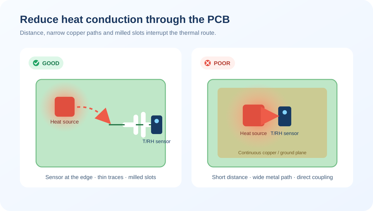
Large ground planes should not bridge the heat-source zone and reference-sensor zone without analysis. The electrical design still has to meet EMC, ESD and signal-integrity requirements, so thermal isolation should be coordinated with circuit design instead of achieved by removing copper indiscriminately.
Housing and Airflow Design Around the Sensor
Airflow determines which temperature the sensor actually sees. The preferred arrangement exposes the T/RH element to incoming ambient air before that air passes over warm components. A partition can separate the reference channel from the CO2, TVOC and power section, while a dedicated outlet allows internally heated air to leave the enclosure. The opening must also avoid a stagnant pocket that slows response.
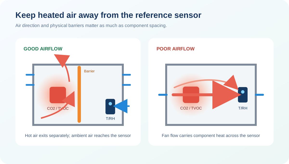
The fan is used to keep sample air moving through the module, not to blow directly on components for cooling. Its airflow should bring representative room air into the sensing path without carrying heat from the PM, CO2 or TVOC section toward the temperature and humidity sensor.
How MAXMAC Designs Multi-Sensor Thermal Zones
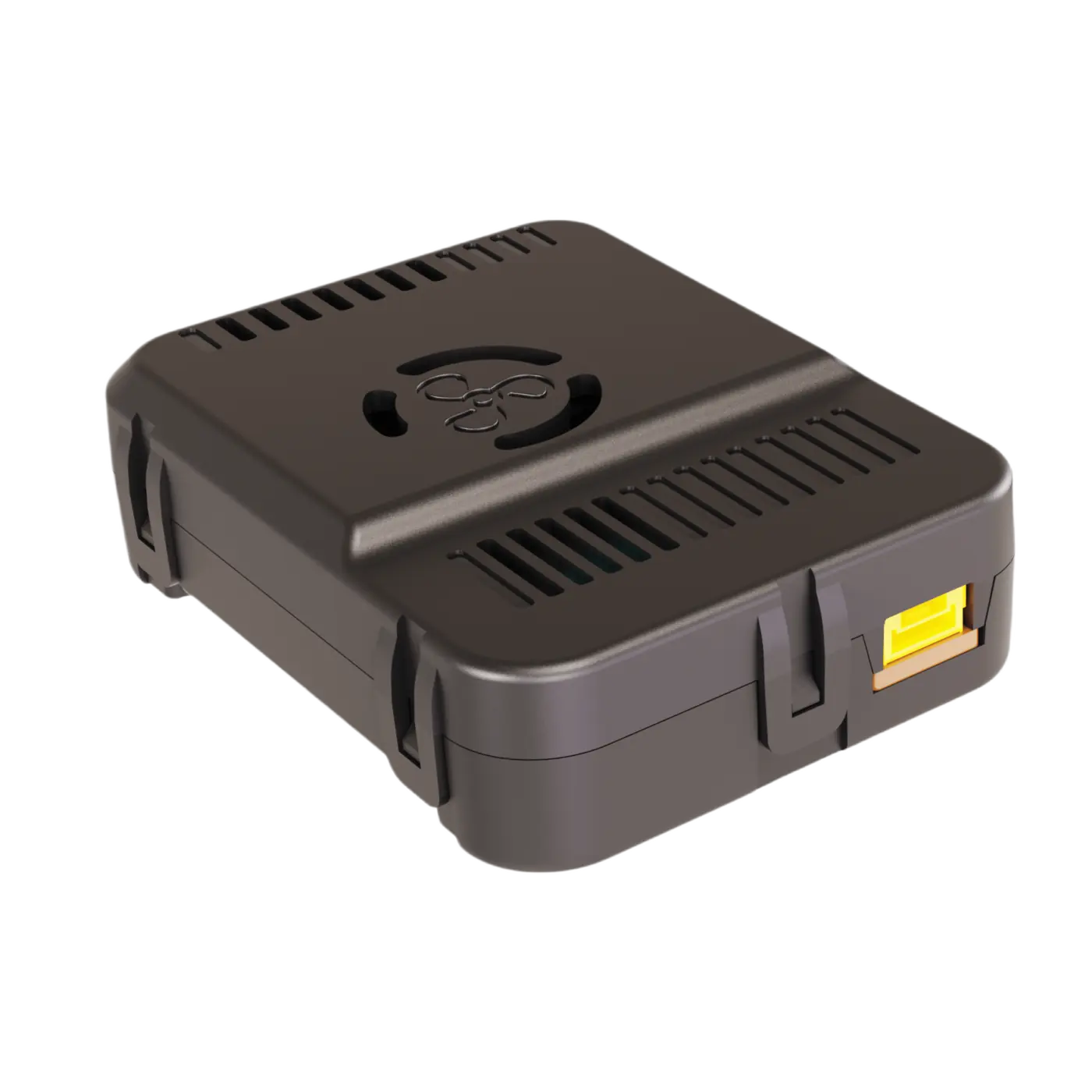
For an integrated CO2 + PM2.5 + TVOC + temperature and humidity platform, MAXMAC treats the PCB and enclosure as coordinated thermal zones. The hot zone contains the NDIR source, TVOC heater and power components. The controlled-flow zone contains the PM optical chamber and fan. The reference zone places the temperature and humidity sensor close to fresh ambient air and away from the exhaust path of the other sensors.
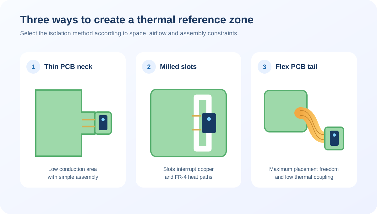
Whatever isolation structure is selected, it must create a clear thermal break between the main board and the reference sensor while still allowing ambient air to reach the sensing element. The sensor should remain mechanically secure behind a protected opening, so dust, condensation and radiant heat are controlled without slowing its response.
Temperature Compensation and Module-Level Calibration
Physical design should remove as much thermal influence as possible before software correction begins. MAXMAC models the remaining offset as a temperature response rather than applying a single correction to every operating condition. The algorithm follows how the complete module warms and settles, correcting the residual thermal offset without masking a weak PCB or airflow design.
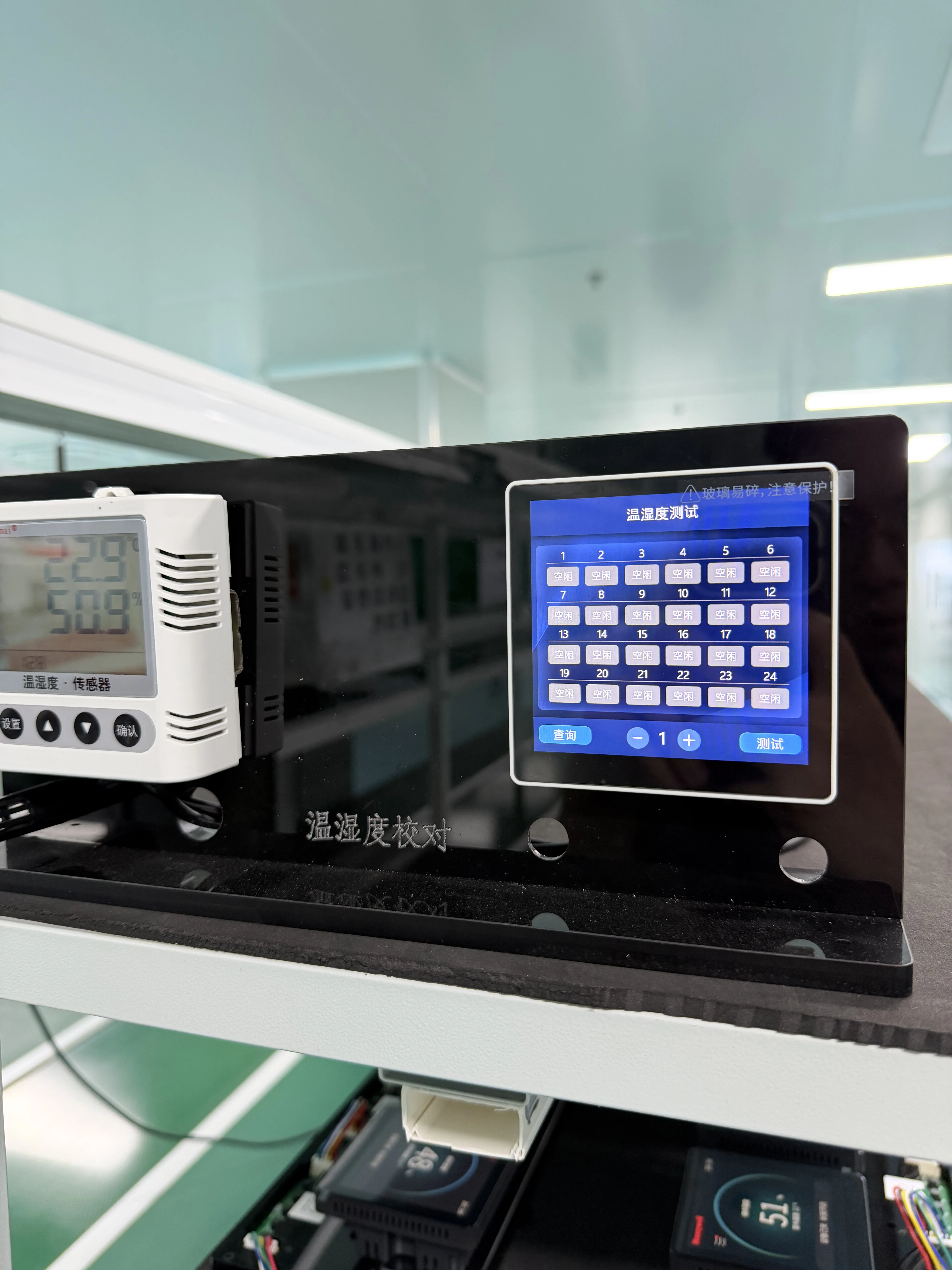
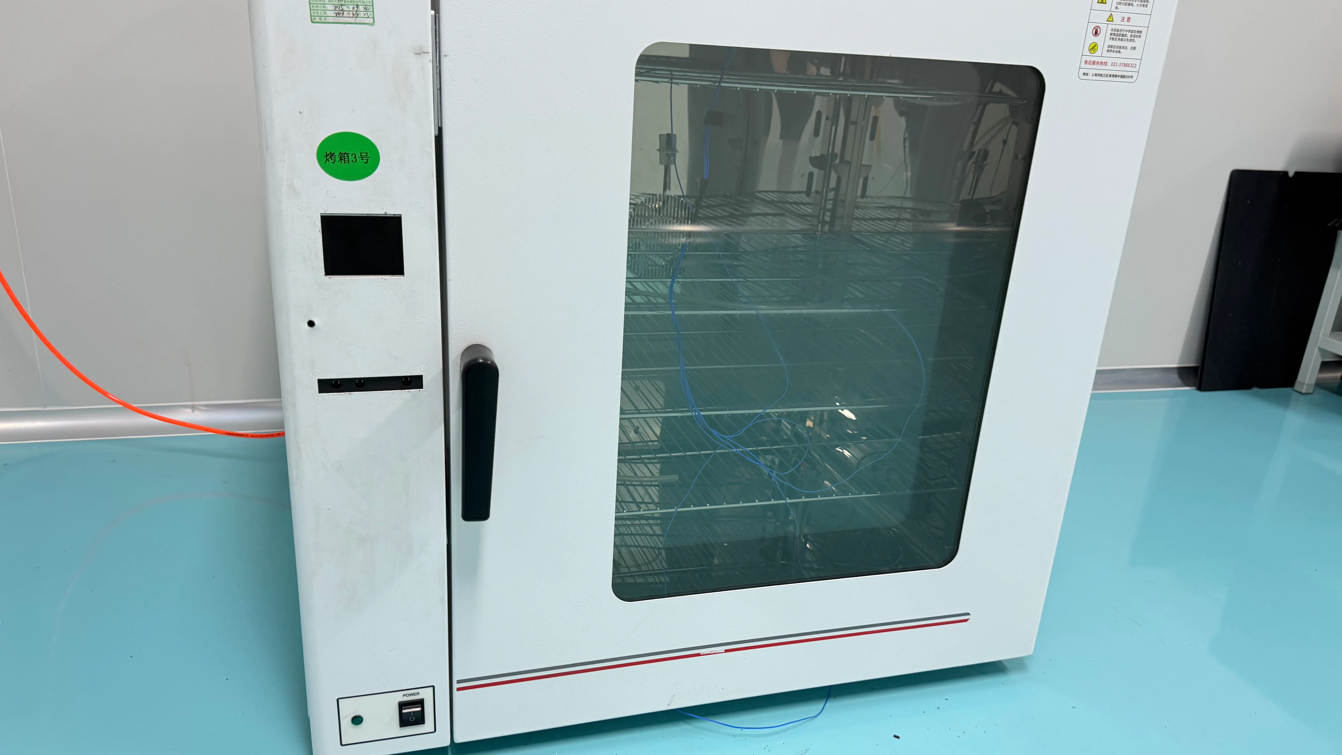
MAXMAC therefore calibrates the assembled module, where the sensors, enclosure and airflow interact exactly as they will in use. Our calibration system records the module's temperature response against a controlled reference as it reaches its normal operating condition. That response becomes the basis of the compensation model, allowing the corrected temperature and humidity output to represent the surrounding air rather than heat generated inside the product.